Master the design and verification of next gen transport: Part Three – functional safety
This is the third part of a series on mastering the design and verification of next generation automotive systems and concentrates on achieving functional safety.
Previous installments have addressed the broad advantages offered by high-level synthesis and emulation (Part One) and an HLS demonstrator using the Tiny YOLO convolutional neural network (Part Two).
Using the same demonstrator, this article will consider the functional safety within the terms of those areas covered the ISO 26262 standard, as shown in Figure 1.
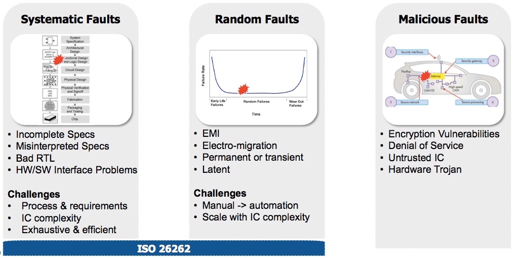
Figure 1. Functional safety fault types (Mentor/Accellera)
At the heart of the process described is a workflow that should reduces systematic and random faults to a standard-compliant level. It has three main stages.
- Safety analysis – calculating safety vulnerabilities and identifying ways to resolve them.
- Design for safety – inserting safety mechanisms and performing initial verification.
- Safety verification – generating, selecting, inserting, simulating, analyzing and verifying the removal of faults across a design so that standard compliance can be documented and certified.
Figure 2 shows how various design and verification activities around functional safety for an automotive design will typically be located within a traditional high-level synthesis flow (HLS).
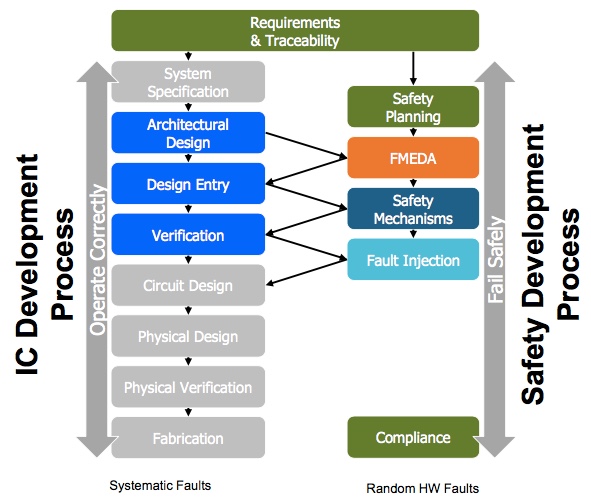
Figure 2. Functional safety in an HLS workflow (Mentor/Accellera)
The underlying assumptions used for the Tiny YOLO demonstrator in an automotive context are shown in Figure 3. The main objective is to demonstrate that by using this workflow this CNN, as earlier refined, can be further enhanced for compliance with ASIL-B, the second lowest safety integrity level defined within ISO 26262.
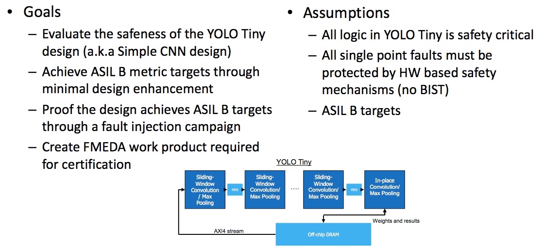
Figure 3. Goals and assumptions for Tiny YOLO case study (Mentor/Accellera)
Safety analysis
The Failure Mode Effects and Diagnostic Analysis (FMEDA) required within ISO 26262 involves the generation of estimated (analytical) and proven (verified) metrics.
A key step during analysis is to compute the failures-in-time (FIT) metric. FIA is based on a standard formula (Figure 4). Here specifically, it is carried out on each sub-block and filter within the nine-stage Tiny YOLO architecture. The results are rolled up to give a FIT number for the entire design, addressing permanent and transient issues.
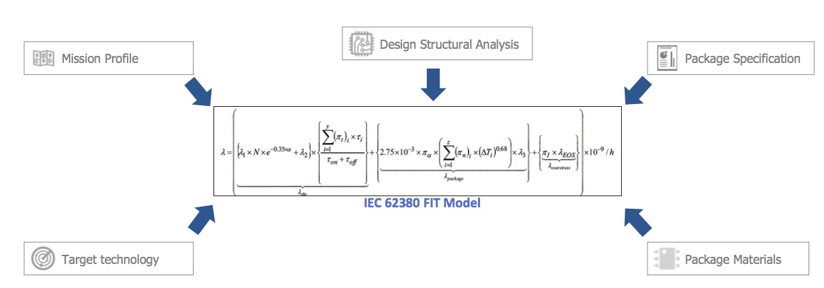
Figure 4. FIT computation (IEC)
These metrics help to provide a better safety-led understanding of the results in RTL after HLS synthesis. To that end, while a total Tiny YOLO FIT rating has been produced, more granular component data within that can help to identify which design instances should first be addressed by the addition of new safety mechanism (Figure 5).
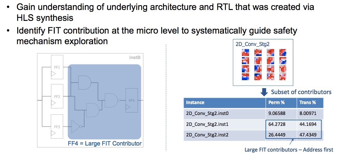
Figure 5. Identifying larger FIT contributors to resolve first (Mentor/Accellera)
The next step is then to evaluate the diagnostic coverage achievable for those mechanisms so that it also informs any safety-led additions made to the design. In Figure 6, for example, the application of safety mechanisms to memory is considered.
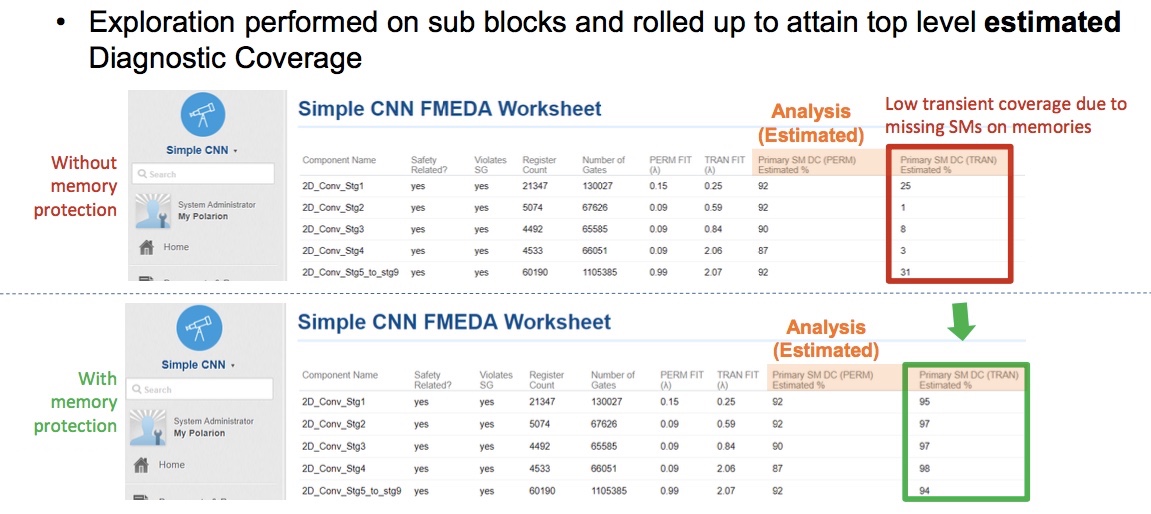
Figure 6. Analysis before and after proposed insertion of memory protections (Mentor/Accellera)
Design for safety
Given the range of safety mechanisms available, the guidance provided during the earlier FIT-based analysis is important. Pulling together a design’s basic requirements for power, performance and area, its use model and its target safety level is complex, even for a comparatively lower level target such as ASIL-B.
As seen above, memory protection has been recommended as a valuable step, so error correcting code is now applied to the Tiny YOLO design to protect it against transient issues (Figure 7).
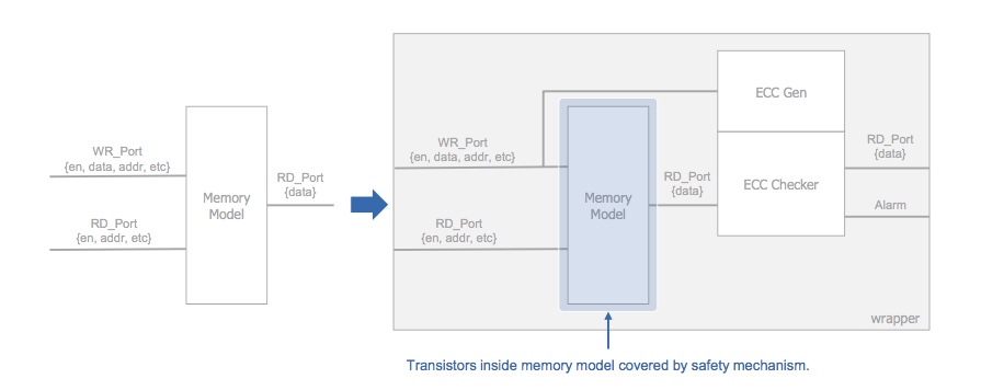
Figure 7. Adding ECC to protect memory from transient issues (Mentor/Accellera)
Other parts of the earlier analysis suggested that a mix of register parity and duplication mechanisms would also help the design hit its funcational safety target. That kind insertion can be performed automatically at the sub-block level.
Safety verification
The Tiny YOLO example has been analyzed and safety mechanisms have been inserted. The next step is to carry out a fault campaign that verifies the results in the context of the original analysis and subsequent design optimizations.
Part One of this series cited how Toyota CEO Akio Toyoda said that some 14.2km of effective test would be needed to verify a fully autonomous vehicle for functional safety and other performance metrics at the system level. But even at the silicon (or, here, CNN) levels, tens of thousands of faults need to be executed on a design to verify that it contains appropriate systematic and random functional safety protections.
The overall fault campaign flow that used for the Tiny YOLO demonstrator is shown in Figure 8. It begins with optimization steps, both at the stimulus level and at the fault list level.
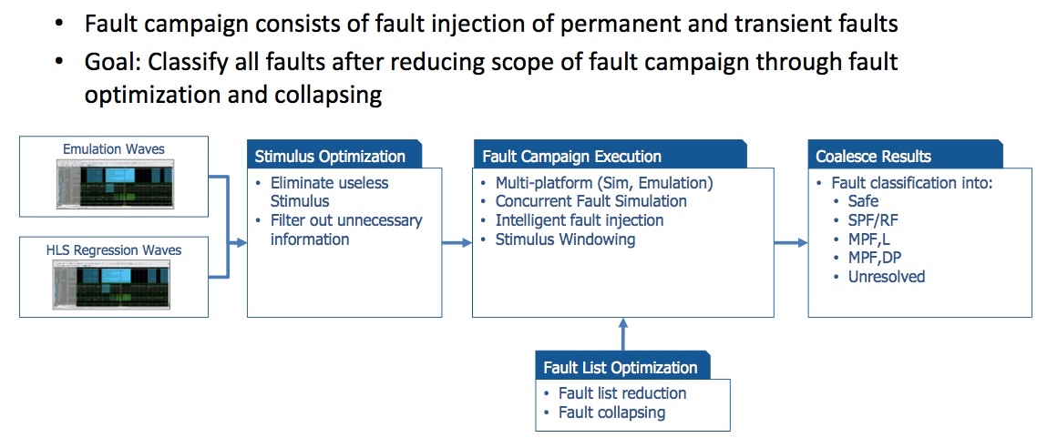
Figure 8. Fault campaign overview (Mentor/Accellera)
Strategies for stimulus optimization (Figure 9) and fault list optimization (Figure 10) are shown separately below.
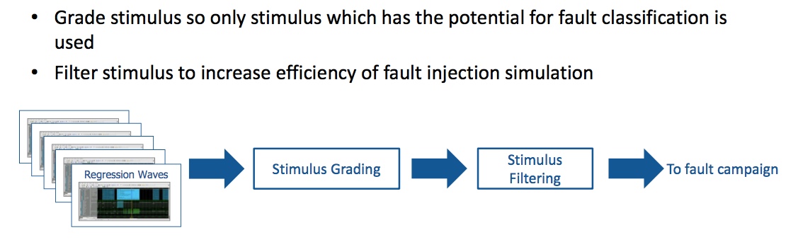
Figure 9. Stimulus optimization (Mentor/Accellera)
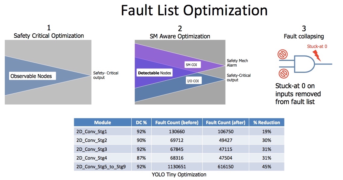
Figure 10. Fault list optimization (Mentor/Accellera)
Techniques such as concurrent fault simulation and intelligent injection can deliver still further efficiencies at this stage when run through a campaign manager that parallelizes and distributes tasks as appropriate (Figure 11).
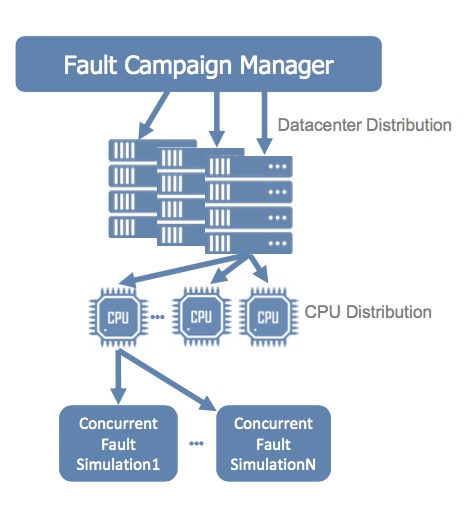
Figure 11. Fault campaign manager (Mentor/Accellera)
The result of this workflow should be full and efficient fault classification and verification ready for addition to the FMEDA for the design. The team can thus report compliance with the functional safety ASIL-B requirements of ISO 26262.
Overview
This functional safety workflow leverages extensive automation and uses a range of tools from Mentor, a Siemens business. The article and the demonstrator within it are based on a tutorial by three of the company’s technical staff, David Aerne, Jacob Wiltgen and Richard Pugh (it will be presented in full at the forthcoming DVCon Europe and can also be found in proceedings from DV Con United States, earlier this year)
A breakdown of the tools used – as well as those that can be used at the lifecycle management level for functional safety projects – is shown in Figure 12.
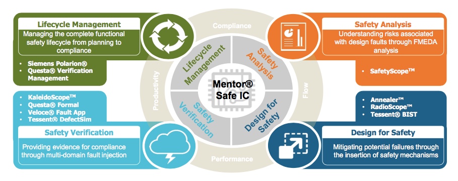
Figure 12. Mentor tools mapped to the Tiny YOLO functional safety workflow (Mentor)
Next steps
The fourth and final part of this series moves on from the comparatively discreet implementation described here to consider the system-of-systems challenges facing next generation transportation, with specific reference to how emulation can be used at that level.