Simplify and accelerate PV debug using default results data views
As technology node scaling continues, integrated circuit (IC) designers face increasing physical verification (PV) challenges due to reliability issues such as electrostatic discharge (ESD) and electrical overstress (EOS).
At the same time, there is a growing complexity in the physical structure of the designs themselves due to the use of multiple power supplies, unique topologies to improve power and performance, increases in raw transistor count, and more. To combat the impact of these changes, foundries and IC design engineers create checks that use EDA verification software, such as the Calibre PERC reliability platform from Siemens EDA for reliability verification. Design teams execute Calibre PERC reliability checks during the design’s physical verification phase to ensure that their circuits will function as intended once they are fabricated, and that they are properly protected against the impact of issues such as ESD and EOS.
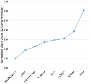
Recent trends point to a drastic increase in the number and complexity of checks being performed as process nodes scale downward (Figure 1). Beyond this growth in checking complexity, however, just the way in which these checks are run can present its own challenge. In a large organization, CAD engineers are typically responsible for providing rule decks that contain various combinations of checks to the designers. Designers run these rule checks against intellectual property (IP) in ther design to ensure it complies with the requirements specified in these checks. However, even though a reliability rule deck will target a range of reliability issues – e.g., ESD, EOS, voltage-aware design rule checking (DRC), suboptimal layouts, etc – all the checks are often run simultaneously within the same verification run.
These amalgamated runs present organizational challenges to the designers and physical verification engineers who debug the output results.
Once a Calibre PERC run is complete, designers use the Calibre RVE viewer to review results in the context of their IP to identify problems in their designs that must be fixed. Occasionally, there are violations that do not need to be fixed because they will not significantly affect either the circuit performance or the manufacturability of the design. When error results do not require debug and correction, designers can waive these results.
However, designers and PV engineers reviewing error results often do not have the context knowledge or authority to waive errors, or even to determine the severity of the violation they are checking. When they encounter an error of which they are unsure, they must consult subject matter experts in their companies who have the authority to apply waivers. These experts, who often have minimal knowledge of the Calibre PERC tool and Calibre RVE interface, must first search for the errors they care about in a plethora of results, and then debug those errors using an unfamiliar interface.
The speed and efficiency with which a root cause can be identified is often highly dependent on how results data is viewed. When creating rule checks, CAD rule deck writers have a specific intent for the way they organize and present results. However, this intent is sometimes not communicated clearly to the design teams. As a result, this communication gap frequently results in an inefficient and ineffective debug process for each check and check type. Each person performing debugging during PV will often manually configure the Calibre RVE interface to create a results display intended to support their optimal debug solution. Unfortunately for design companies, both situations end up extending the time and resources required for debugging.
Finding a solution
To help resolve this problem, CAD teams could implement default views in the Calibre RVE results viewer for each scenario. This approach would give the rule deck writer a consistent and repeatable way of incorporating the preferred display formats for presenting different checks and results to the designers running these checks. There are several Calibre RVE features that can immediately help simplify the PV debug experience for designers, while other options would require thoughtful consideration while creating rule checks.
Separate checks by category
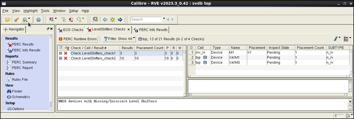
When rule deck writers create a deck, they should be able to classify or separate checks by category and display every category in a separate Calibre RVE tab. This classification will enable the physical verification engineer to put a rule deck through a single run that contains a variety of checks — e.g., level shifter checks (detect domain crossings with missing level shifters), EOS checks (identify devices at risk for EOS due to overvoltage conditions) and ESD checks (ensure devices are protected in case of an ESD event). This single run will provide an organized Calibre RVE results view that enables SMEs responsible for each category within it to review more quickly and fix or waive results associated with their respective areas of expertise (Figure 2).

Figure 2. Separating checks from different categories into their own tabs in the results view helps speed up error debug (Siemens EDA)
Group results using tree views
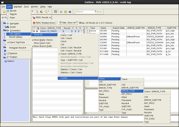
If many results are generated because of the sheer size of an intellectual property (IP) block in a layout, the ability to group them with a particular tree view (Figure 3) can further simplify the identification and contextualization of the results. For example, a designer grouping the results by cell > check instead of check > cell could quickly and easily pinpoint all violations within a particular IP.

Figure 3. A tree view display within the Calibre RVE results viewer speeds up debug of selected subgroups of results, such as those associated with an IP block (Siemens EDA)
Control amount and order of error data
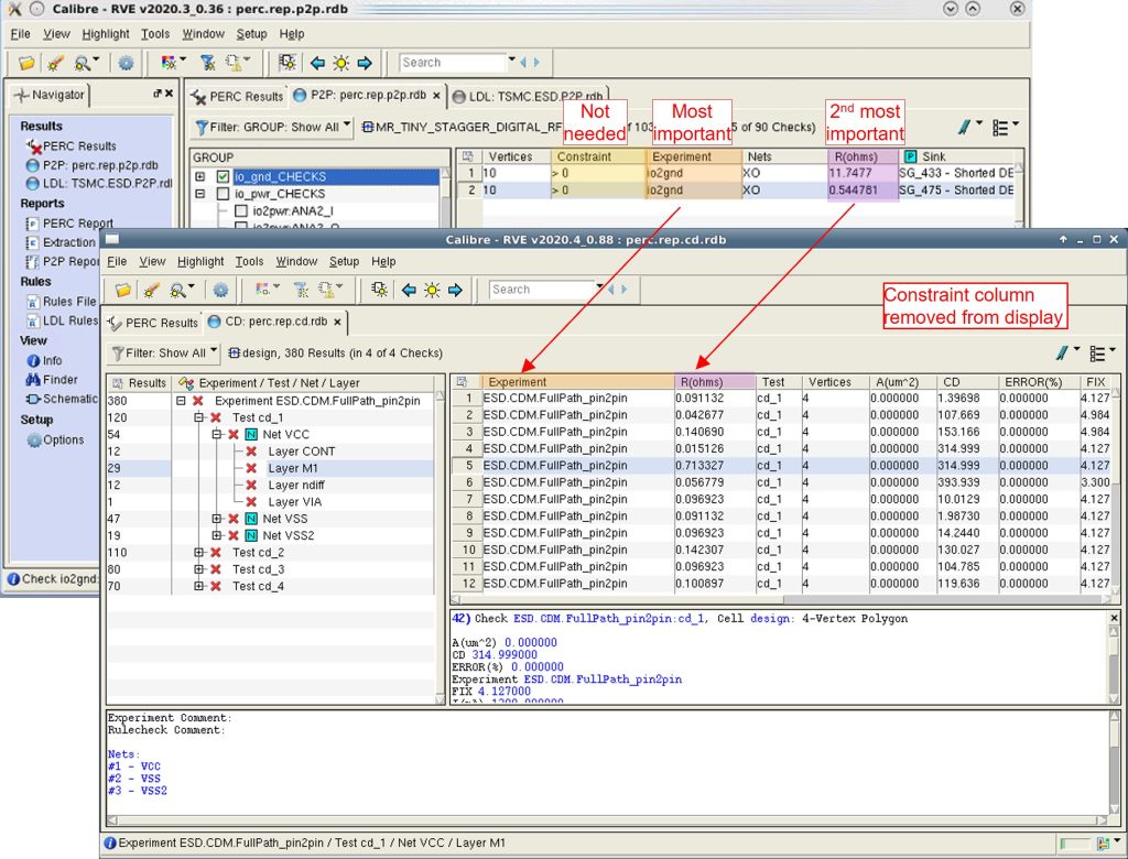
Rule deck writers for PV could create a default view within the Calibre RVE results viewer that defines which data to display for a particular set of checks. They could also use this default view to control the ordering of the displayed data, which would allow for critical information to be displayed without going through a lot of clicks of a mouse (Figure 4).

Figure 4. Controlling the amount and order of error data simplifies and speeds up debug (Siemens EDA)
Summary
As physical verification checks grow in quantity and complexity, and IC designs become more intricate, PV error debugging has become more challenging and time-consuming. The addition of default view definitions in a results viewer can make the process of debugging faster and easier, reducing turnaround time for every iteration. Reducing time spent in reviewing and debugging error results enables design teams to reduce time-to-tapeout while also reducing the risk of suboptimal performance or, worse still, a post tape-out failure of the chip.
For a more detailed discussion, read or download a copy of our paper, Standardized and customizable results display makes error debugging faster and easier.
 Neel Natekar is a senior product engineer in the Design to Silicon division of Siemens Digital Industries Software. Prior to joining Siemens, Neel worked as a design engineer focusing on power delivery solutions for custom CPUs. He received a B.Eng. in Electronics and Telecommunications from the University of Mumbai, and an M.S. in Electrical Engineering, Circuits and Microsystems from the University of Michigan.


