Capturing connectivity for assembly verification in 2.5D and 3D design
Successful 2.5D and 3D system development is tricky. A new technical article addresses one of the more challenging aspects: How can you capture assembly connectivity needed for assembly verification when the final design includes key data from different teams and suppliers that can also be in multiple formats.
For example, the decomposition of SoCs into chiplets is often pushing multi-dimensional integration back to silicon interposers that were previously considered too expensive. Now, by contrast, they are seen as a better candidate where a design is composed of these multiple units of custom and off-the-shelf IP. The resulting SoC will, however, typically emerge as a Verilog netlist.
Meanwhile, at the substrate and packaging level, the separation of the work may complicate the process with part being done by a foundry and part by an OSAT. They may have no common PDK, and even if just the foundry is involved, this information can emerge in a .csv file format.
Indeed, there are other formats to potentially consider within a 2.5D/3D project: text, LEF/DEF, OBD++.
The paper, ‘System-level connectivity management and verification of 3D IC heterogeneous assemblies’, describes a stage that can consume abstracts for die, interposers, packages and PCBs to help the project verification leads get at those connectivity issues on the way to full assembly verification.
It describes a flow based on the Xpedition Substrate Integrator (xSI) platform from Siemens EDA. As author Tarek Ramadan explains, it ingests the various abstracts (with Verilog support a recent addition) for the engineers: “Then they can interactively view and modify the full assembly connectivity and, eventually, export a system-level assembly netlist that can drive assembly verification.”
The paper sets out this process and how it integrates with the Calibre 3DSTACK platform in a single flow (also shown in Figure 1): “xSI has a plug-in that allows the system-level designer to utilize the information stored in the xSI database to automatically generate a complete Calibre 3DSTACK run set (full assembly description and comprehensive assembly checks) along with a system source netlist.
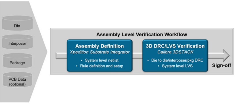
Figure 1. Integrated assembly verification workflow (Siemens EDA – click to enlarge)
“This designer-centric approach is agnostic to the different die technology nodes, the different substrates involved in the assembly, and the different manufacturing vendors (for example, a silicon interposer from foundry X and an organic substrate from OSAT Y).”