Three key ways to reduce silicon test costs
The cost of silicon test is becoming a real headache again as multibillion-gate designs become more common.
Advances in compression have helped keep problems at bay until recently. Mentor Graphics’ Tessent family is the test market leader. When it launched TestKompress in 2001, it offered a 10X compression ratio. Over the years, that ratio has risen toward 100X.
“We’ve kept pace, and we’ve added new technologies,” says Greg Aldrich, Marketing Director for Mentor’s Silicon Test Solutions. “As a result, we’ve customers who’ve said, ‘[Compression] is what ‘s allowed us to keep the same testers for the last decade. The designs have been getting bigger, but as we’ve been able to increase the compression level, we haven’t had to change the hardware. And the test times have remained stable.’
“But that’s changing. Designs are growing in size a lot faster than before. Rather than gate-count doubling every two years, you’re now looking at it happening every 12 months. Billion-gate designs aren’t the leading edge; they’re becoming normal. We had a fairly typical customer come to us just six months ago with an 800 million-gate design.
“Cost is never off the agenda but because of that it’s becoming a big issue again.”
Much of the cost-down work Mentor has undertaken has concentrated on automated test pattern generation (ATPG). It’s easy to see why.
Typical generation has long been based on waiting for your final gate-level netlist, and flattening it to generate the patterns. “But you can’t take a billion-gate design and do that anymore,” Aldrich notes. “You need a massive number of CPUs. You need massive memory. And it will still take months to generate the patterns. All that time, you have people screaming that they want to get to tape-out. It’s just not practical.”
Over the last two or three years, Mentor has progressively rolled out enhancements to Tessent that address this and other cost issues, particularly the increasing parallel importance of automotive silicon design.
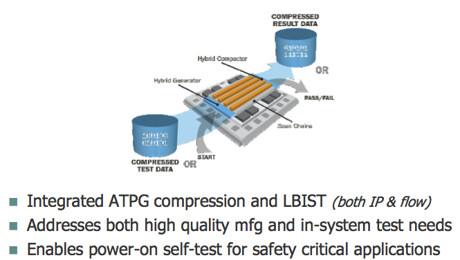
The first has been a hierarchical flow, breaking down these huge designs and eliminating duplicated effort. The second, unveiled just a few weeks ago, is a new compression strategy that offers a novel spin on an established technique: test points. The third, initially for that growing number of automotive players, is a hybrid implementation of embedded compression and full logic built-in-self-test (BIST).
Hierarchical ATPG for a billion-gate world
Hierarchical strategies are already used throughout much of the design flow. ATPG is a relative latecomer, although given how well compression has served it that’s not entirely surprising.
Several silicon design houses have already tried to introduce hierarchical test internally, but have not all achieved the efficiencies they wanted.
“Some customers have been working toward hierarchical implementations by taking a whole netlist and just focusing on one core,” says Aldrich. “But that still requires the whole design to be done because you have to figure out, ‘How do I deal with inputs to that core and outputs from it?’ You have to have known values in ATPG. You can’t have unknown states.”
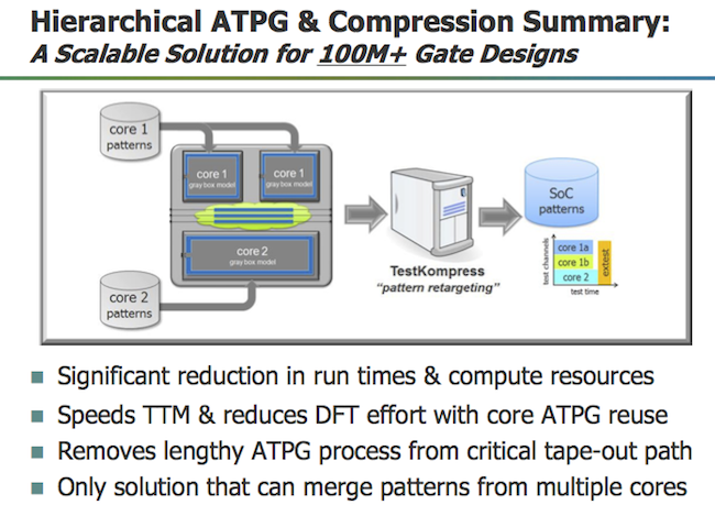
In Mentor’s Hierarchical ATPG flow, the user can isolate each of the cores in a design. Where there are identical cores, patterns are generated only once for each type, only a core-level netlist is used rather than a full one. That generation/black-boxing process is then available regardless of the number of different cores within the design.
“The ATPG is the same each time, but it’s done on a much smaller partition,” says Aldrich. “So it’s very fast. Similarly, some of the cores themselves might be very large – 10 million gates possibly – but you can determine what you send out to your grid for multiprocessing, what you do locally. And the retargeting is a simple lightweight process, minutes on a big design to retarget patterns.
“But what’s unique about our solution is that we then don’t just map the pattern. We don’t require direct scan connections from core to the chip. Instead, we can map this through multiplexing logic. We have mode selections. We can retarget it through retargeting flops and sequential elements. We can retarget through some logic at the top level.
“The other thing is we don’t just retarget one core type at a time. We can merge the patterns into a single test, so you’re working on all of them in parallel. You can target all the cores together and merge them into a single set of test patterns. That significantly reduces the application time to test this on a device.”
Mentor’s customers seem very happy with the results. One recently presented at the International Test Conference on how it used the hierarchical flow to get pattern generation down from a typical 19 days to just one.
“And those kinds of results don’t just show the simple benefits of a hierarchical approach,” says Aldrich. “Look at it also from the point of view that, if you used to have a three-week run and a machine crashed during that, you had to go back to the beginning. Similarly, you finish the run and find your coverage isn’t enough. Back you go again. Those are the issues that have hit tape-out schedules.”
Mentor says average user results for the hierarchical flow have been:
- A 5X reduction in ATPG generation time
- A 5X reduction in memory
- A 50% reduction in pattern count
- 100+ hours reductions in gate-level simulation
A good start, but there’s more.
Rethinking test points for pattern count
Test points have traditionally been coverage-driven: How do I get better observation or more control over a particular node? Inserting them to overcome the limitations of the pseudo-random patterns used in logic BIST is a typical and long-standing use-case. This October Mentor added the Embedded Deterministic Test (EDT) Test Points feature to Tessent TestKompress. Its rather different goal is the reduction of pattern count.
The conceptual thinking behind EDT Test Points is straightforward. What took the idea a while to come to market was a need to accumulate enough data to construct the underlying algorithms for wide use on typical designs.
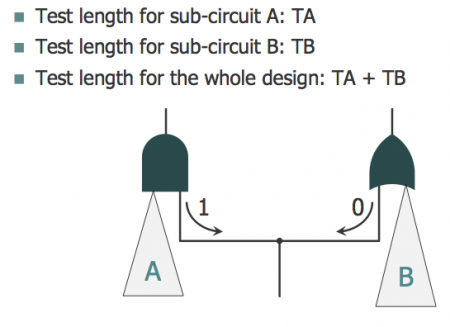
Consider Figure 2. The logic cone comprised of A and B feeds into an AND gate and an OR gate. It is easy enough to test. In terms of controllability and observability, there is no need for a test point. Set the value to ‘1’ and you can test everything from A. Set it to ‘0’ and you can test everything from B. But as shown there is a ‘pattern count conflict’. The total test time will be TA plus TB. As it stands, you cannot test this in parallel.
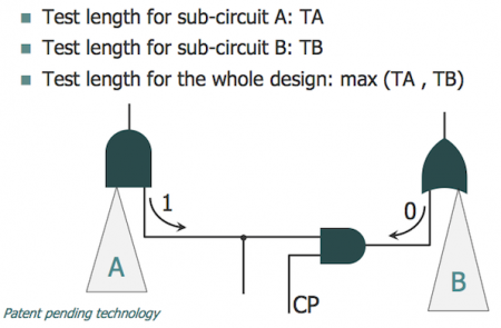
Now consider Figure 3. Here a control point has been introduced and this allows for the two to be tested in parallel. It’s not ‘necessary’… unless you consider that this potentially reduces test time by 50%. Looking at a design from this point of view is what the EDT Test Point concept does, but in a far more sophisticated way.
“If you are going to do something like this, you need new algorithms. To develop those, a huge amount of heuristics is involved,” says Aldrich. “We needed to see hundreds of designs, and not just those but also hundreds of different styles to tune the algorithms so that we could say they work in the majority of cases.”
Developing such a necessarily comprehensive feature required two years of work and beta-testing with some lead clients. “At the beginning, we saw some design implementations where we got significant improvement immediately but there were some where we got nothing. It took a while. What made this happen is that we got a lot of data to look at,” says Aldrich.
Another important issue was real estate. How much did an EDT Test Points implementation require to be added to the design? The more data Mentor could harvest the less that became.
Similarly, it became clear that the benefits the feature could offer varied according to the issues in the circuitry: “Customers tend use EDT Test Points on blocks where there are pattern-count issues, outliers with very high pattern count,” says Aldrich. “Those are typically the ones where you get better reductions. It is very design dependent.”
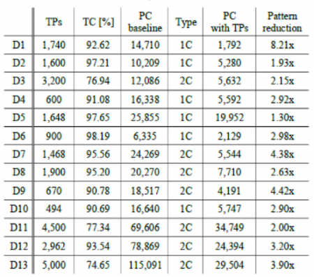
A number of those early pathfinder users have published data on their experiences using EDT Test Points. These point to reductions in pattern counts of between 2X and 9X. Supporters of the technique include Marvell, Broadcom and even the normally reticent Intel (at least when it comes to publishing its EDA vendor results).
Those kinds of results have been achieved with test point additions somewhere in the range of 1 to 2% of total scan flops.
“One customer translated this to a 0.5 to 1% area impact, typically at the lower end, says Aldrich. “And another nice thing is that the technique is working on all pattern types: stuck-at, transition, cell aware, and so on.”
One final and particularly persuasive aspect of EDT Test Points is that its benefits come as a multiplier on top the existing compression level. So, if a company is getting compression in the 85-100X region, and can get a 3-4X mid-range count reduction by adding the points, that points to scan volume reductions in the 400X range overall.
A hybrid BIST and compression technique for automotive test
Much like Mentor’s work with test points, the automotive-aimed Hybrid TK/LBIST feature for safety-critical applications is based on leveraging existing technologies more efficiently.
“If you look at embedded compression and logic BIST from a circuit POV, there are a lot of similarities,” says Aldrich. “In fact, when we developed TestKompress, we did so with an eye to reusing some of the logic for a complete BIST.”
What has brought the two techniques together now is the very specific demands of the automotive market, particularly within the structure of the important ISO26262 standard.
“Look at automotive’s requirements in their context: zero defects going out of the manufacturing floor; then later on, for safety purposes, the ability to make sure the system is still defect-free every time you run a power cycle,” says Aldrich.
“So to expand on that: For manufacturing where you have access to a tester and you want the highest quality, you need a very deterministic test. You need to be able to target specific fault models if you want zero DPM. But if you want a quick in-system test, something that runs a test when you power on the system, logic BIST is the ideal solution. You don’t need any memory; you just need a power-on signal that comes back with a pass/fail.
“Previously, customers had to implement TestKompress. And then they would have to implement logic BIST, put all the multiplexers in and have a multiplexing network to choose between them. Two separate implementations. We can provide those in a single solution. And we’re doing it both from the IP point-of-view, where you are serving a decompressor and compactor for BIST – and also from the flow point-of-view – where you implement once and get both solutions.”
This solution has been around now for a couple of years, but continues to gain a lot of new interest as the number of players looking ambitiously at automotive and its demands on design also continues to grow.
“This could hop over to avionics. Obviously, you have DO-254 and its requirements,” says Aldrich. “The problem with avionics, though, is that it’s a very small market. Automotive is somewhere you’re now seeing companies you never thought would be in that space: Nvidia, Intel, Broadcom, Qualcomm. And then you have the established players: Renesas, NXP, Panasonic, Toshiba.
“With that kind of target market, this solution is doing really well for us.”
* The data in Figure 4 originally appeared in the paper ‘Embedded Deterministic Test Points for Compact Cell-Aware Tests’ presented at the 2015 International Test Conference by authors from Intel, Mentor Graphics and Poznan University of Technology.
