How Mentor realized concurrent engineering for PCB design
Concurrent engineering (or ‘concurrent design’) is a buzz phrases at the moment. If done properly, it promises to shorten projects and help companies meet time-to-market. The time freed up can also be used for more work on optimization and/or verification. Better products delivered more quickly. Who would argue with that?
But concurrent engineering is easier said than done. In trying to reach this goal, managers often find that they need to partition and then reassemble projects. It is likely they will have different specialists even within a discrete part of the process. In the PCB world, you might have your WiFi expert, your Bluetooth expert and so on. You also have those who are specialists in schematics, layout, power and signal integrity and, again, so on.
The problem with partitioning and reassembly is that they can be lengthy tasks. The time savings may therefore not be as great as you had expected. Moreover, they are also error-prone tasks. That raises the risk of late-stage ECOs.
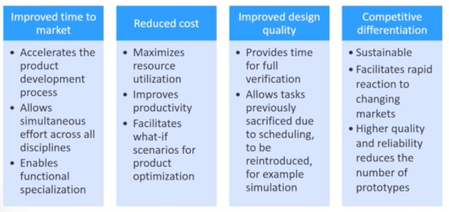
The benefits of concurrent engineering (Mentor – A Siemens Business)
Craig Armenti, a PCB marketing engineer with Mentor, A Siemens Business, has lately been grappling with these issues. In a series of blogs and a webinar, he describes how his company has sought to deliver real concurrent engineering across its Xpedition Enterprise tool suite.
You can consider his thoughts in detail by following the links posted toward the end of this article, but here we run through a few of the key rules (or, if you prefer, objectives) that Mentor applied when upgrading Xpedition.
What makes Armenti’s observations particularly interesting is that they apply to concurrent engineering in two regards.
Tool-based concurrent engineering is where multiple team members working within the same domain and using the same tool (e.g., system design, schematic design, constraint management and PCB layout) are made capable of working on the same design object simultaneously.
Flow-based concurrent engineering is where multiple team members working in different domains and using different tools within an interoperable suite are made capable of working on the same design object simultaneously.
The latter is considered the most efficient, truest form of concurrent engineering. The concepts that make either work are, however, broadly the same. There are six in all.
Tentpoles of concurrent engineering
1. Multiple users must have concurrent access.
This is self-evident, but serves as a useful reminder that for flow-based engineering, this objective must be achieved across not only multiple users but also multiple design domains.
2. Real-time restriction/locking of areas under edit.
It is always possible that even within a single design domain being worked on by a number of experts, there may be some crossover in areas that each wishes individually to address. Nevertheless, once one user has checked out an area to make changes (or is in the process of adding a constraint/notation), it must be blocked to others.
3. Real-time visibility of additions and edits to the design or its constraints.
Once a change is made it must be reflected across the project immediately, otherwise there is the possibility of a design conflict. Such conflicts need to be prevented by instant, automated updates to the design files.
4. Visible feedback and communication/notification.
Within a single design domain, other users may be locked out of portions of a design that colleagues are currently working on. But have they noticed a change and can they see what is happening? Familiarity with the task is no guarantee, so the whole team needs to see any changes whether or not they are working in that section of the project simultaneously. This observation applies doubly for team members from different domains – they need a clear indication of what has changed or needs to be reviewed. In Xpedition for example, this is done by traffic signals (green and amber) in the status bar. This shows a change needs to be reviewed and acknowledged.
5. An ability to simulate and analyze the design.
Flexibility must include an ability to look at ‘what if’ scenarios and functional simulation in portions of the design available for edit.
6. Flexible documentation.
Why has a change been made? In a concurrent engineering environment, all team members can work across a project simultaneously, notwithstanding the need for locks. So, it follows that more than one member may change a section that would previously have been in a single user’s partition. That member must be able to explain the change to his colleagues.
Best practices for concurrent engineering
As noted, Craig Armenti discusses these ideas further in a series of blog posts and a webinar:
He also summarizes some best practices for realizing a successful concurrent engineering strategy. These are:
- Ensure all team members have access to a tool suite that truly supports a team-based design model.
- Communication is still essential. In a concurrent flow, any action taken in any tool has the potential to impact everyone on the design team.
- Disruptive updates, such as a significant ECO, should ideally be coordinated to minimize design cycle interrupts that impact all members working concurrently.
- Everyone has their own design style. Team members should resist the urge to recreate/change the work of others, lest the gains of concurrency are quickly lost.
One final point does have to be made. Mentor had the luxury, if you will, of enabling concurrent engineering in Xpedition’s case because it is the single vendor of a suite that encompasses many different competences.
For most flows – and particularly outside the PCB world – there are typically multiple vendors each providing a best-in-class solution (as the client sees it) to a highly complex problem. This kind of integration will, in those cases, still require a lot more work and cooperation.