Speeding up simulation using native System Verilog transactors
A webinar just posted by Synopsys lays out a strategy for accelerating simulation using native System Verilog transactors to ease the transition from a pure software-based approach to one that uses a combination of software and Synopsys ZeBu-3 hardware emulation.
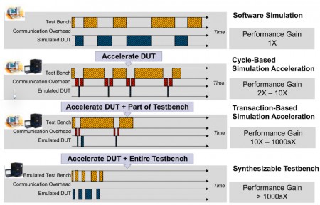
In the webinar, Parag Goel, a senior CAE in the verification group at Synopsys, lays four approaches to simulation.
Figure 1 Four approaches to faster verification (Source: Synopsys)
Of these four:
- The simplest approach runs both the device under test (DUT) and its testbench in a software simulator.
- Cycle-based simulation acceleration runs the DUT in an emulator and exercises it using a testbench run in a software simulator. Communications between the hardware and the software environment happen on each tick of the simulation clock, but the throughout of the overall set-up is limited, in part, by the communications between the two environments.
- Transaction-based simulation acceleration runs the DUT and part of the testbench in the emulator. Communications to the rest of the testbench, hosted in the software simulator, are at the transaction level and less frequent than in the precious scenario. The transaction-level interface between the two enables higher performance, as well as the use of System Verilog and UVM constructs.
- With a synthesisable testbench approach, both the DUT and the full testbench run in the emulator, for maximum speed. This approach, though, limits the use of advanced testbench languages and methodologies, such as constrained random verification, because the testbench has to be synthesisable.
Goel goes on to outline the relative performance of these approach, as in figure 2 (below).
Figure 2 Comparing the performance of the various approaches (Source: Synopsys)
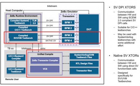
He goes on to lay out the Synopsys ZeBu-3 based approach to transaction-based simulation acceleration.
Figure 3 A ZeBu-based simulation acceleration environment (Source: Synopsys)
In this approach, the whole flow is governed by a unified compilation approach (see bottom middle), which communicates with, and controls the host computer running the ZeBu runtime environment, which in turn communicates with the ZeBu-3 emulator.
Communications between the host computer and ZeBu-3 are done in two ways:
- Using SCE-MI 2.0 compliant System Verilog DPI transactors
- Using native System Verilog transactors
Using native System Verilog transactors enables the creation of a unified simulation and emulation environment, so that simulation tests can run on the ZeBu-3 emulator without change. This approach also enables greater reuse of System Verilog and UVM-based testbenches and testbench components to build emulation-specific tests.
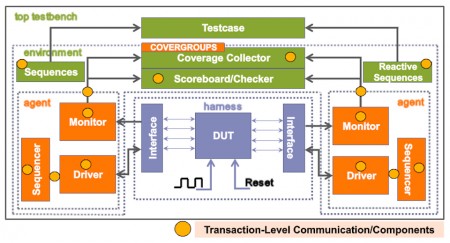
Goel illustrates a typical UVM testbench environment, highlighting the transaction-level communications and components, as follows:
Figure 4 A typical UVM testbench set-up (Source: Synopsys)
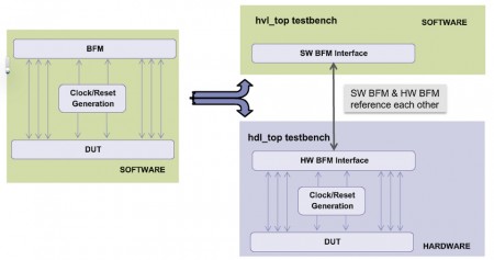
He then walks through an approach to splitting the testbench into two parts: a timed, synthesised part to be run as hardware on the emulator, and the other verification components that need to run in the simulator.
Figure 5 Partitioning the testbench (Source: Synopsys)
The bus-functional model also needs to be split in a similar way, to separate the transaction-level and signal-level activity.
Goel then uses a series of code snippets to show how to establish communications between the hardware and software aspects of the testbench, and similarly to establish communications between the two different representation of the bus-functional model. This section of the webinar also covers issues such as how to manage the data-type conversions necessary for accurate communications between the two domains.
The rest of the seminar explains, with code snippets, how to partition a verification environment using transactors. Goel argues that, done properly, this should enable a design and its verification testbench to be moved easily from a software simulation environment into a mixed environment that includes an emulator.
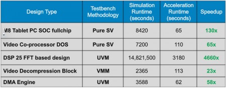
He also shows why such an approach is worthwhile with this table of example runtimes in simulation and emulation.
Figure 6 Comparing runtimes for simulation and emulation-based approached to verification (Source: Synopsys)
For full details, you can access the archived webinar here.

