Automate latchup verification for 3DIC
The use of 2.5DIC and 3DIC system-in-package architectures has many attractions, such as the ability to mix and match process technologies for different cores in an SoC. But implementing them calls for changes in the way teams approach the design process, particularly in the creation of I/O cells and the protection circuitry they need to guard against ESD and latch-up.
Latchup is problematic as transient pulses can lead to long-lasting current surges that destroy onchip circuitry and causing the IC to fail. As a result, I/O-facing circuit paths need to obey design rules that prevent the parasitic bipolar transistors that cause latchup from forming.
Even in the conventional 2DIC environment, the verification of latchup protection circuitry can be difficult to achieve. This becomes more complex in the 3DIC environment where it is unclear at the level of an individual IC whether each interface will lead to an external path or another chiplet.
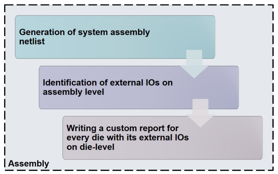
Image Latchup analysis for supported by Calibre PERC
In 2DIC design, the most common method used to identify latchup-sensitive paths to use manual layout markers. It is error prone as the markers are easy to misplace. Accurately managing a manual layout markers methodology becomes even more difficult and time-consuming in 2.5D and 3D designs. It would be better to have an automated method for capturing and recording this information for use in verification.
What is needed is a tool-supported systematic methodology that is able to identify paths that need latchup protection. A white paper from Siemens Digital Industries Software shows how this can be implemented using the Calibre PERC reliability platform.
Using the layout of each die and any interposers as inputs, the latch-up verification flow automatically differentiates between external I/Os and internal I/Os, without the use of layout markers to drive the analysis. Though it is preferable to have complete layouts for dies that are free from basic DRC and LVS errors, this is not an absolute requirement. It is possible to work with partial layouts as long as they contain all the geometries that must be verified, and the right connectivity to die ports.
Using that automatically gathered information, Calibre PERC generates a netlist for analysis that reflects the inter-die connections and those that lead to the external package. The tool then identifies any potential latchup injectors and performs DRC checks so that it can report violations that need to be debugged.
The result is an automated latchup protection verification scheme for 2.5DIC and 3DIC designs, improving the reliability and product life of these products.