Win on the fault campaign trail with formal
How formal verification for the ISO26262 automotive functional safety delivers the full activation, propagation, and observation in the form of proven and exhaustive results.
When verifying a system on a chip (SoC), you need a reference that represents correct behavior of the chip or block. Using simulation, this reference can be a behavioral or C model or a UVM testbench. The test environment compares the behavior of the SoC with the behavior of the reference and if they are equivalent, the test passes. The reference can also be coded as SystemVerilog assertions and verified using simulation or a formal property verification tool. If the assertions always hold, the verification test is passing.
In this context, comparing a design to itself doesn’t sound very useful because the reference and design under test (DUT) is the same. However, using sequential equivalence checking (SEQ) this can be a very meaningful and important test because it can find issues caused by unknown values that would otherwise be caught much later by gate-level simulations.
A common application of SEQ is to verify that inserting clock gating into a design, as shown below, does not alter the function of the design. In this case there are two designs, one with clock gating and one without, and the purpose of SEQ is to verify identical functionality pre- and post-clock gating.
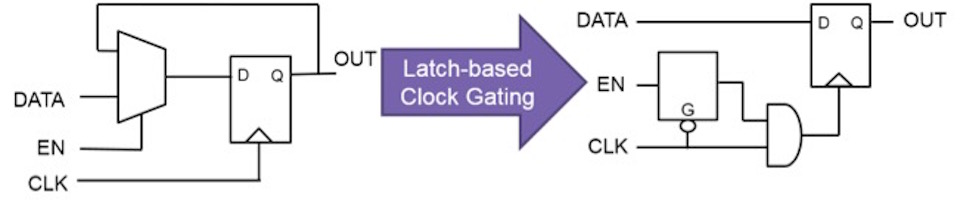
Figure 1 Comparing a design before and after insertion of clock gating (Source: Synopsys)
A sequential equivalence tool verifies that the outputs of a module or SoC are the same on every clock cycle, given that the inputs are the same. The behavior between clock edges may be different as long as the outputs are the same at the clock edge. This is different from Boolean equivalence checking, where the logic driving outputs and flip flops have to be functionally equivalent. Conceptually it is like the difference between a cycle-based simulator and an event-based simulator.
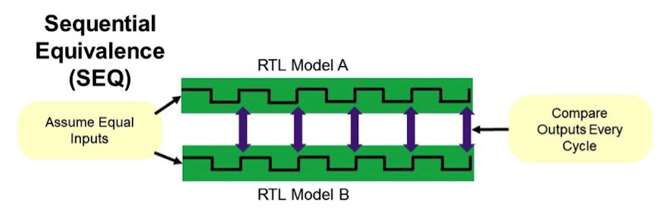
Figure 2 Sequential equivalence checks compare outputs at every cycle (Source: Synopsys)
Other examples of applications of SEQ includes retiming changes and functional changes that don’t alter the output behavior – but these also include two different versions of the design.
What else can I verify by proving sequential equivalence between two copies of the same design, when there are no changes between the two versions?
For a comparison to be useful there must be differences in the two copies of the same design. As we’ll see, there actually may be real functional differences. If the design has uninitialized registers, i.e. registers with unknown values, this means that the registers may end up with different values after reset since they are not constrained. Now you suddenly have two different designs, since they are in different states, and this may lead to functional differences.
Many designs have uninitialized registers and still work fine. If the uninitialized registers are in the data path, they will get a known value as soon as data is passed through the device, and it will work as intended. However, if the uninitialized registers are in control logic, it may affect the behavior of the design. The unknown values may propagate and finite state machines (FSMs) may start in illegal states, control registers may allow illegal behaviors, and outputs may drive illegal values. A design which starts in an illegal state or has random values at outputs may violate security or safety requirements of the device in addition to being functionally incorrect.
Other causes of failures due to unknown values are explicit X assignments in the RTL and array-bound violations. If sigB has a value greater than 3 in the code below, the assignment to memOut is unknown because the memory memA is addressed outside the defined range.
wire [2:0] sigB;
reg [1:0] memA [1:0];
wire [1:0] memOut;
assign memOut = memA[sigB];
If this unknown value propagates to an output, we’ll see a difference between the two copies of the design since the formal tool may assign different values to memOut in the two cases and the proof fails. This is also the case with explicit X assignments in the RTL. Assignments of variables in the RTL to X allow the synthesis tool to optimize the code, and if the code is un-reachable or an arbitrary value does not affect the output of a module, everything is fine. However, if the X assignment leads to different output values in the two copies of the design, we may see functional failures in the chip.
In simulation, this can be verified by enabling X propagation in the RTL simulator or by running gate-level simulations. The advantage of using formal tools is that they exhaustively check all cases.
For example, if the register “Reg” in the figure below is not initialized, it will be X or unknown. This means that the formal tool may assign it any value, i.e. it may take the value “1” in the first copy and “0” in the second copy of the design. This means that the logic that affects the output “OUT1” in the two cases is different. If other logic prevents the value of “Reg” affecting the value of the output, it is safe to leave the register un-initialized. However, if the outputs are different there is a problem since the random reset state leads to different behaviors in the two copies, and hence, the output value is not deterministic.
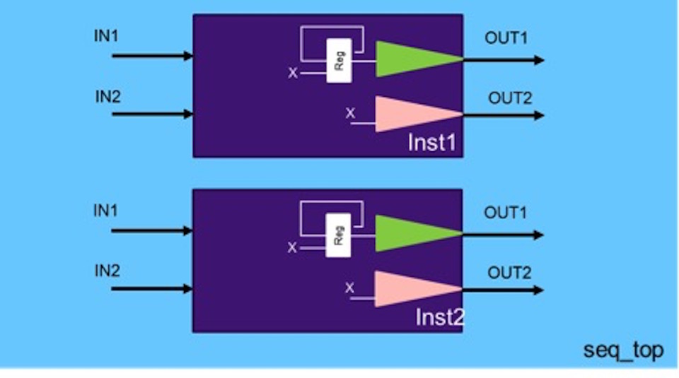
Figure 3 Random reset states can lead to different behaviors in two copies of a design (Source: Synopsys)
Comparing a design to itself using formal-based sequential equivalence checking is a powerful way to detect X propagation caused by un-initialized registers. SEQ verifies partial reset designs by proving that X cannot reach outputs. If not caught, this situation may lead to intermittent incorrect behavior, and may also violate security and safety properties of the design. These are only two examples where equivalence checking is critical – there are of course many more.