Formal fault analysis for ISO 26262: Find faults before they find you
How to use formal fault pruning, injection and sequential equivalency checking to meet the FMEA analysis requirements of the functional safety standard.
Automobiles are becoming computers on wheels – more accurately, multiple complex mobile computing systems. The safety of highly electronic vehicles depends increasingly on the quality and correct functionality of electronic designs.
The automotive safety standard ISO 26262 requires that objective hardware metrics are used to calculate the probability of random hardware failures and mandates specific remedial steps in the case of a failure to meet safety criteria. Hardware architectures must be rigorously tested to ensure they meet functional safety requirements dictated by the standard. It states that this analysis should include Failure Mode and Effects Analysis (FMEA). Fault analysis is used to measure and verify the assumptions of FMEA.
Fault injection is an essential component of fault analysis. However, traditional applications of random fault injection in gate-level simulation eat up too much time and require late architectural changes. Thus, it is important to begin this process earlier in the design cycle by moving to higher levels of abstraction, such as the register transfer and transaction levels.
Yet at higher levels of abstraction we still run into similar problems with random fault injection: It is inefficient and time-consuming. This is true even when using hardware emulation and design prototypes.
To overcome these limitations, the focus must be on faults that are not insulated by safety mechanisms and that will subsequently cause safety failures.
The answer lies in formal verification fault analysis using a combination of formal fault pruning, fault injection, and formal sequential equivalency checking.
By leveraging formal technology, we can determine the number of safe faults by identifying the unreachable design elements, those outside the cone of influence (COI), or those that do not affect the outputs (or are gated by a safety mechanism). After fault pruning, the optimized fault list can be used for fault injection. Formal verification conclusively determines if faults are safe or not, making the failure rates from formal analysis more comprehensive than fault simulation. These strategies are discussed in detail below.
Culling the verification space
We want to improve the efficiency of any fault injection mechanism. To do so, static analysis is performed ahead of time to determine the critical set of design elements where faults should be injected. At the same time, we can remove design elements that are not critical to the safety mechanism. We call this ‘fault pruning’. The primary objective is to skip elements that will not affect the safety requirement and focus fault injection on elements that will.
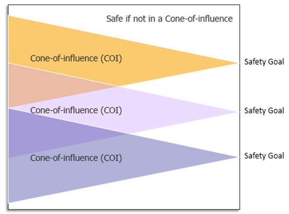
As part of a ISO 26262 safety analysis and based on the safety requirement, an engineer defines the safety goals and the safety critical elements of a design. A formal tool has the ability to trace back from the safety goals through the design elements to determine what is in the cone of influence (COI) See Figure 1.
The steps in the fault-pruning process can be summarized as:
- Identify a set of safety critical elements in the design that will have an immediate impact on the safety goals. These include output ports, state machines, counters, configuration/status registers, FIFOs, and other user-specified
- Create a list of constraints for the block. Examples can include debugging mode, test mode, and operational modes not used in a specific instance. However, for this list to be valid, its constraints must have an independent safety mechanism (An example is an error flag that is generated whenever the design sees these modes are active). Typically these modes are global and their safety mechanisms are addressed at higher levels.
- Compute the COI of these safety critical elements and create a fault injection list based on elements in these fan-in cones. Design elements that are not in the COI are considered safe and need not be considered.
- Apply formal techniques to verify that faults injected in these elements will be observed and will impact the safety goals and/or safety critical
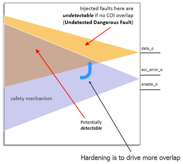
The next step is to look at what design elements in the COI of a safety requirement overlap with the COI of the safety detection mechanism. For example, suppose the data integrity of a storage and transfer unit is considered safety critical. As shown in Figure 2, along with each data packet, there are error-correcting code (ECC) bits for detecting any error. As long as the ECC bits can flag any transient fault, the data output is protected because errors can be detected and dealt with downstream. However, in a dual-point fault situation, error(s) may also be affecting the ECC detection logic. As a result, the safety mechanism is prevented from detecting bad data in the packet.
In this case, the first fault in the safety mechanism is considered a masking condition and thus a latent fault. The second fault in the dual-point fault scenario is an actual error that the safety mechanism would have detected if not for the latent fault, thus leading to a dual-point failure.
Besides, not all design elements are in the COI of the safety mechanism. Design elements that are in the COI of the data output but not in the COI of the ECC logic will not be protected by the safety mechanism and so must be considered potentially unsafe. Faults in these design elements are treated as undetectable or potentially unsafe. As a result, we have:
- Design elements (in the COI of the ECC) where faults are potentially detectable by the safety mechanism (safe, residual faults, or dual-point faults); and
- Design elements (out of the COI of the ECC) where faults are undetectable by the safety mechanism and potentially unsafe (residual faults).
With the ability to measure the two COI, the opportunity to improve the design (hardening) becomes apparent. A large ‘undetectable’ section of the two cones means that there is a higher percentage of elements that can lead to residual faults. As a result, the ability to meet high ASIL ratings is significantly reduced. The goal of the design team at this point is to determine how to create more overlap of the safety critical function and the safety mechanism.
Injecting faults
Once the number of design elements in the fault list have been pruned down to a high quality and meaningful subset, it can be passed onto various fault injection mechanisms; such as fault simulation, hardware accelerated fault simulation, formal fault verification, and hardware prototyping.
Even though most simulation regression environments deliver high functional coverage, they are poor at propagating faults to the output ports. Also, the functional checks are not robust enough to detect all kinds of faults. We create the regression environment to verify the functional specification – i.e., the positive behaviors of the design. It is not designed to test the negative behaviors. We are interested in formal-based fault injections primarily because of two attributes:
- Fault propagation: For example, a random fault has been injected into the FIFO registers that causes its content to be corrupted. As the simulation environment is not reactive, the fault can be overwritten by subsequent data being pushed into the FIFO. Formal verification is different. It injects faults intelligently. It is good at introducing faults that it knows how to propagate to affect the safety goals or outputs of the design.
- Fault detection: For example, even when the corrupted FIFO content has been read, the fault may not be detected. The FIFO content may be discarded because the functional simulation is not in the mode to process the data. Most functional simulations test the scenarios that have been defined in the specification, while fault detection requires testing all the scenarios that may go wrong (negative behavior) consistently. To check all potential negative scenarios, we rely on formal sequential equivalency checking (FSEC).
FSEC compares the outputs of two designs or two representations of the same design. The implementation of the two designs can be different as long as the outputs are always the same. For example, FSEC can be used to compare a VHDL design that has been ported to Verilog (or vice versa) to see if the two RTL designs are functionally equivalent. Conceptually, an FSEC tool is a formal tool with two designs instantiated, constraining the inputs to be the same, and with assertions specifying the outputs should be equivalent for all possible internal states.
While there are many uses for FSEC, fault injection is a sweet spot. Formal tools have the ability to inject both stuck-at and transient faults into a design, clock the fault through the design’s state space, and see if the fault is propagated, masked, or detected by a safety mechanism. Once the fault is injected, the formal tool tests all possible input combinations to propagate the fault through the design to the safety mechanism — this is where FSEC becomes necessary.
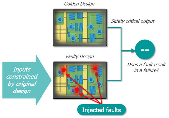
As depicted in Figure 3, a golden (no-fault) model and a fault-injected model are used to perform on-the-fly fault injection and result analysis. Fault injection with formal FSEC is useful early in a design cycle when no complete functional regression is available. It can be used to perform FMEA and to determine whether the safety mechanism is sufficient. Designers can experiment and trade off different safety approaches quickly at the RTL. Such approaches include error detection, error correction, redundancy mechanism, register hardening, and more.
By instantiating a design with a copy of itself, all legal input values are automatically specified for FSEC, just as a golden reference model in simulation predicts all expected outputs for any input stimulus. The only possible inputs are those values that can legally propagate through the reference design to the corresponding output. By comparing a fault-injected design with a copy of itself without faults, the formal tool checks if there is any possible way for the fault to either escape to the outputs or go undetected by the safety mechanism.
The steps of the fault injection with FSEC can be summarized as:
- Specify two copies of the original design for FSEC. The input ports will be constrained together and the output comparison will be checked
- Run FSEC to identify any design elements — such as memory black boxes, unconnected wires, un-resettable registers, — that will cause the outputs to be different. Constraints are added to synchronize them.
- Use the fault list to automatically specify possible injection points in the faulty design. Normally, we will focus on the single point faults – e., one fault will be injected to check for equivalency.
- Based on the fault list and the comparison points, FSEC will automatically identify and remove any redundant blocks and
- Run FSEC concurrently on multiple servers. The multi-core approach has significant performance advantages as multiple outputs can be checked on multiple cores concurrently.
- Use a technology to compile all the faults in one single run, and thus save time and space resources usually needed for compiling the faults one by one.
- Run the FSEC verification step for thousands of faults in one single run.
- If an injected fault has caused a failure at the comparison point, a waveform of the counter-example that captures the fault injection and propagation sequence can be generated for debugging.
Results
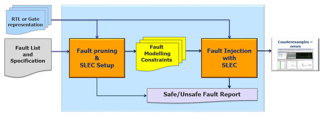
We have assembled an environment for formal fault pruning and fault injection with FSEC, summarized in Figure 4. The fault-pruning step builds a netlist representation of the design. Based on the safety goals (that may be just the output ports) and the safety mechanisms, a formal method is then used to compute and examine the COIs. Safe and unreachable faults are reported. Fault injection with FSEC is done using the Mentor Questa Formal Verification tool. Before running fault injection, users can control the locations and the types of faults to be injected using the fault modeling and constraints. In addition, users can partition the design or configure the tool to perform the injection runs on a multi-core server farm environment.
Formal fault pruning – Case 1 results
The design is a float point unit with approximately 530K gates. The goal is to identify the safe faults in the design. These faults are outside the COI or cannot be propagated to functional outputs regardless of input stimuli. The original fault list contains approximately 32K faults. After compilation and set up, 868 of them were identified as safe faults. Interestingly, due to the mode of operation, 690 of them cannot be propagated and will not affect the outputs of the design.
Formal fault pruning – Case 2 results
The design is a memory management unit with approximately 1.3M gates. The goal is to identify faults that can propagate to internal status registers. These registers are checked by safety mechanisms at a higher level. Hence, these detectable faults can be considered safe. In the design, there are 71 status registers and 1524 faults in the targeted fault list. After compilation and set up, 720 of them were identified as safe faults within an hour.
Formal fault injection – Case 1a/1b results
The design is a clock controller block with a safety mechanism implemented with triple modular redundancy (TMR). TMR is an expensive, but robust, on-the-fly safety mechanism. For a quick preliminary test, faults were allowed to be injected to all the registers in the design (Case 1a). As all the registers are in the COI of the safety mechanisms, there is no surprise. Formal fault injection verifies that all the injected faults will be caught by the safety mechanisms. Next, faults were allowed to be injected to all the nodes (registers, gates, and wires) in the design – there are significantly more faults (Case 1b). Again, formal fault injection verifies that all the injected single point faults will be guarded by the safety mechanisms.
Formal Fault Injection – Case 2a/2b results
The design is a bridge controller that consists of the clock controller block from Case 1. In this case, formal fault injection was able to inject and propagate some faults to the output ports of the design. Two types of faulty scenarios were observed:
- Single point faults that were not protected by any safety mechanism
Residual faults that were protected by safety mechanisms; however, the safety mechanisms did not detect the error conditions correctly.
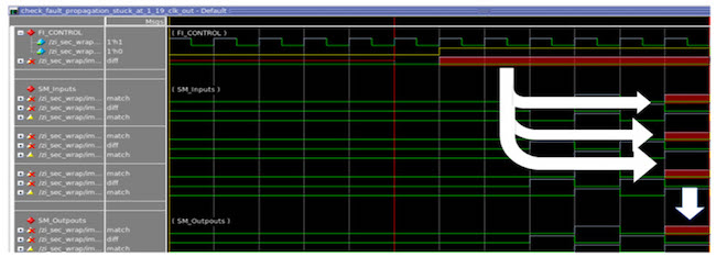
Figure 5 shows a scenario of Case 2 where the injected fault was missed by the safety mechanism and violated the safety goal. A random fault was injected shortly after reset removal. This fault had caused multiple errors in the design, and they reached the outputs of the design after five clock cycles. Unfortunately, the safety mechanism was not able to detect these errors. As a result, the fault has caused
a violation of the safety goal.
About the authors
Ping Yeung is a Verification Technologist at Mentor, a Siemens Business, Doug Smith is a Verfication Consultant at Mentor and Abdelouahab Ayari is a Euro App Engineer – Digital Design & Verification Solutions at Mentor.
