Take advantage of the automated refactoring of design and verification code
 Tom Anderson is a technical marketing consultant working with multiple EDA vendors, including Agnisys. His previous roles have included vice president of marketing at Breker Verification Systems, vice president of applications engineering at 0-In Design Automation, vice president of engineering at IP pioneer Virtual Chips, group director of product management at Cadence, and director of technical marketing at Synopsys.
 Designing and verifying a large, complex semiconductor device is all about coding. Long gone are the days when design meant drawing huge schematics and verification was performed in real time using hand-specified input values with output results observed as waveforms. Sure, there may still be a schematic for an analog function or two around, and waveforms still play an important role in debugging. But the hardware design, the embedded software in a system-on-chip (SoC), and most of the verification testbench are coded.
A typical design and verification environment uses a rich mix of languages, including SystemVerilog, Verilog, VHDL, e, and C/C++, interconnecting all the design and verification elements. Beyond the functional correctness of code, there are numerous attributes that determine how well it can be handled by logic synthesis, compilers, and other tools as well as how easily it can be supported, debugged, and evolved by engineers. Even such simple attributes as consistent alignment and indentation can make the code more understandable and more maintainable, especially when new engineers encounter it.
The process of improving code for better consumption by engineers and tools is commonly called ‘refactoring.’ This process is geared not toward finding or fixing bugs in the code, but instead toward improving comprehensibility and supportability. In practice, refactoring may well reveal bugs that were hidden in the ‘mess’ and become visible by inspection in better code. Although traditional refactoring was largely performed by hand, many refactoring steps for design and verification code can now be automated within an interactive environment.
Refactoring with the IDE
Originally developed for software, an integrated development environment (IDE) is a tool to help programmers develop, test, and debug their code interactively. The scope of IDEs has expanded to support both hardware designers and software engineers as they create designs and verification testbenches. The IDE can support the full range of software programming languages, modeling languages, hardware description languages such as Verilog and VHDL, dedicated verification languages such as e, and both the design and verification features of SystemVerilog. The IDE can:
- Perform many types of checks on the code;
- Highlight and format the code according to user preferences;
- Compile the code to present the complete design and testbench structure;
- Connect to a simulator for debugging failing verification test cases; and
- Provide an intuitive graphical user interface (GUI) for code development.
There is a lot of intelligence at work behind the GUI. The IDE actually compiles the source code and builds an internal database of the design and the verification environment. This allows the analysis of the design and verification code in context, with knowledge of both the languages and libraries (such as the Universal Verification Methodology (UVM)) being used. This database and the extracted knowledge enable automated changes and improvements to the code, all under easy control of the engineers using the IDE.
Examples of automated refactoring
Making code look ‘pretty’ is perhaps the most obvious improvement that the IDE can perform. As mentioned previously, even rather simple formatting changes make code easier to understand, verify, and modify. Although not always considered a form of refactoring, reformatting qualifies because it improves the code while not changing the functionality. Some basic refactoring operations include:
- Automatically indenting the code according to scopes;
- Trimming whitespace from the end of lines;
- Compressing whitespace to a single character (when it does not affect indentation);
- Mixing multiple tabs and spaces in whitespace as specified by the user;
- Adding whitespace before or after specified tokens;
- Wrapping lines that become too long; and
- Wrapping multi-line comments to fit the line width.
While these changes may sound trivial, the automation with the IDE can save engineers many hours of time spent on manual edits needed to conform to company coding guidelines. Deeper knowledge of language syntax and semantics allow the IDE to make more complex code manipulations, including:
- Inserting ‘begin’ – ‘end’ blocks when optional for the statement;
- Placing ‘if’ and ‘else’ constructs on new lines;
- Placing module ports and parameters, function and task arguments, and class parameters one per line or multiple on a single line;
- Indenting single-line and/or multi-line comments; and
- Indenting designated language constructs.
All these refactoring steps, as well as the others discussed in this article, are automated but entirely under the control of the user. Some companies may allow individual engineers to choose their own formatting preferences; others may require use of a company-wide configuration file so that all code looks consistent. Vertical alignment of constructs is another area where engineers often have strong preferences. Table 1 shows several automated alignments that make design and verification code easier to understand and maintain. All of these can be performed by the IDE.
Although the examples provided in this article are focused on SystemVerilog code, the principles of refactoring apply equally to all design and verification languages.
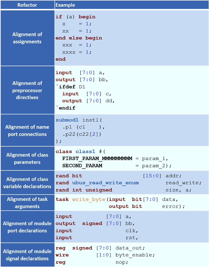
Table 1: An IDE can perform many kinds of vertical alignment refactoring (AMIQ EDA).
In this simplest form of refactoring, the code is changed neither syntactically nor semantically. However, there are refactoring operations that change the code syntactically without altering its black-box functionality. A SystemVerilog front end for any design or verification tool should build exactly the same internal model from the code before and after refactoring. SystemVerilog is a very complex language with a reference manual of more than 1,300 pages. There are many ways to specify equivalent functionality. Flexibility sometimes breeds complexity. Some of these ways are more compact, readable, and maintainable than others. Further, as different project teams may have different coding styles and rules, the ability to refactor can significantly help with following the coding guidelines.
One useful but sometimes confusing flexibility feature of SystemVerilog is that module instance port connections and function call arguments can be specified either by position or by name. The positional syntax has the advantage of brevity, but the code can be difficult to read, especially when containing many arguments or ports of the same type. The named syntax improves readability and it is not sensitive to the arguments or ports order. Figure 1 shows an example of the IDE automatically converting named argument bindings to positional argument bindings. This screenshot and the others that appear in the following examples are from the Design and Verification Tools (DVT) Eclipse IDE from AMIQ EDA.
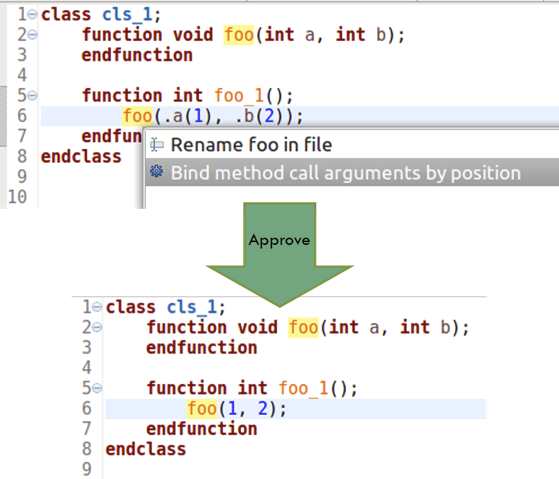
Figure 1: An IDE can automatically convert argument bindings from named to positional (AMIQ EDA).
Being able to switch from one form of argument binding to the other is very useful when doing code clean-up or reusing code from previous projects that followed different coding rules. Figure 2 shows an example of the IDE automatically converting positional argument bindings to named argument bindings. This capability could also be used to unify coding style, or it might be used temporarily to check that function calls or instantiations look correct.
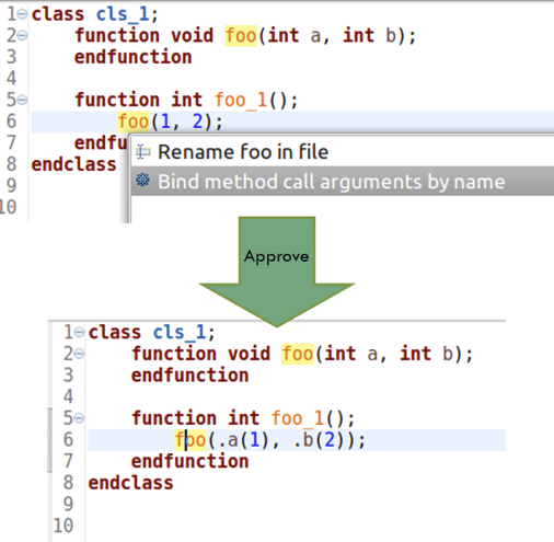
Figure 2: An IDE can automatically convert argument bindings from positional to named (AMIQ EDA).
SystemVerilog also supports the ‘.*’ wildcard operator, which indicates that all ports are implicitly connected to existing identically named signals in the scope of an instantiation. When possible, this is a very compact form, but there are times when a user might want to expand a wildcard to a full port list. Figure 3 shows the IDE performing this refactoring.
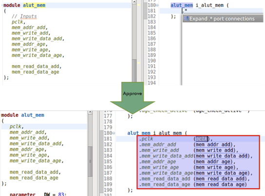
Figure 3: An IDE can automatically convert from wildcard to named argument bindings (AMIQ EDA).
SystemVerilog offers many other options for flexibility. For example, a class method can be implemented within the class itself or just prototyped with an out-of-block implementation. The IDE can automatically reorganize the code to flip between these two options. Figure 4 shows an external method implementation folded into the class, while Figure 5 shows an internal implementation split out as external.
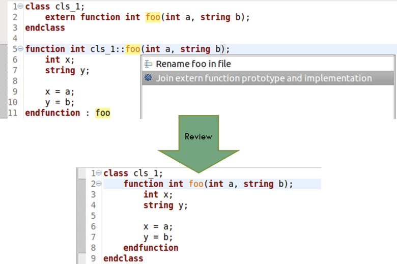
Figure 4: An IDE can join an out-of-block method implementation with the prototype within the class (AMIQ EDA).
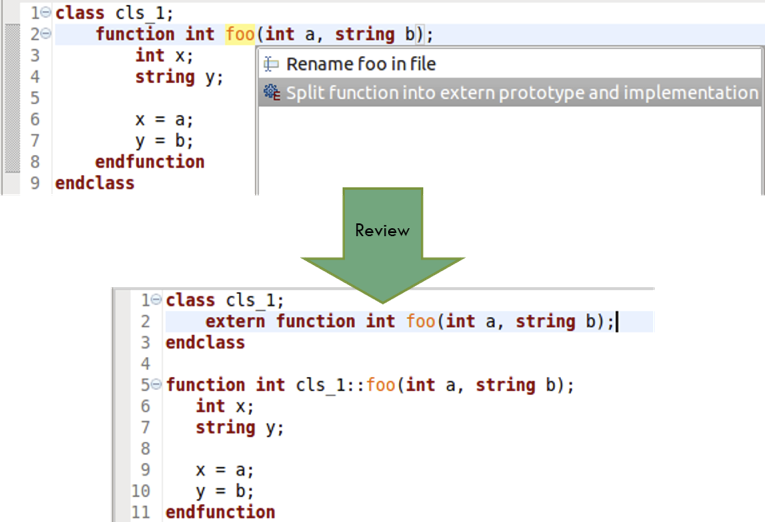
Figure 5: An IDE can split a method from a class into a prototype and an out-of-block implementation (AMIQ EDA).
Another refactoring approach that leads to more compact and more readable code is replacing repeating expressions with local variables. Figure 6 shows an example of using the IDE to make such a change. The expression ‘a+b’ appears several times within the same function, so the user specifies that a new variable be created to replace this expression and then may name this variable as desired.
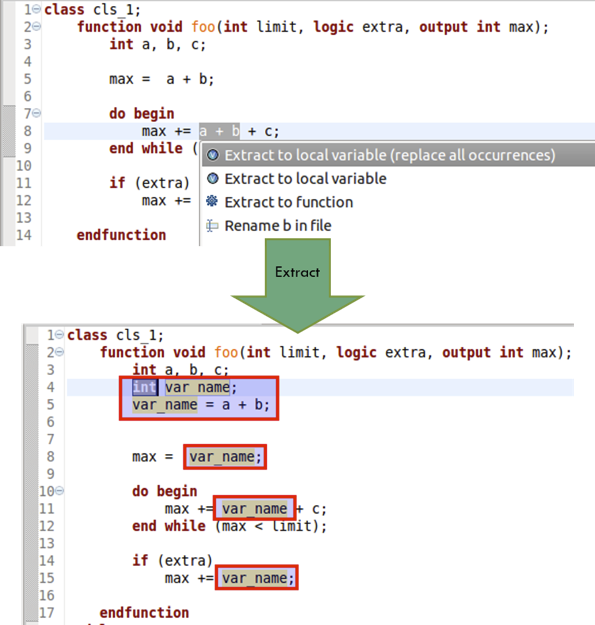
Figure 6: An IDE can automatically extract an expression to a new variable (AMIQ EDA).
Similarly, the user may have a block of code that will be repeated, so converting it to a new function or task would create code that is more compact. With a well-chosen name, the code would also be more understandable. Figure 7 shows the IDE creating a function from a user-specified section of code. The user also selects the name of the new function.
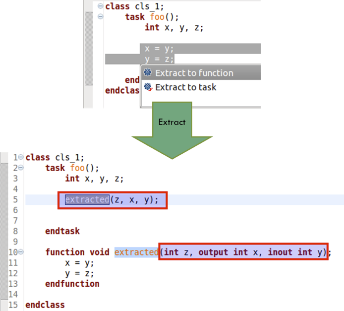
Figure 7: An IDE can automatically extract a section of code to a new function (AMIQ EDA).
Once the new function is created, it is available for use in future coding wherever it makes sense. Engineers do not always start projects with crisply defined libraries. They may discover reuse opportunities as they code, and the ability to refactor and create new reusable tasks and functions on-the-fly is valuable.
Renaming elements in the code is one of the most popular refactoring operations. This seemingly simple task is tricky to perform when using plain text editors to write code. For example, changing the name of a type may involve edits to many files, and text editor searches may require tedious validation because of other elements with similar or identical names. Figure 8 shows how this process can work much better with the IDE. The user selects the element to be changed (in this case, a variable) and types in the new name. The IDE shows all the files that will be affected by the name change and the user can preview the proposed changes in each file. Upon approval, all relevant files are modified automatically, and the IDE’s internal database is updated. The IDE allows users to easily rename many kinds of elements, including module ports, classes, functions, macros, variables, and arguments.
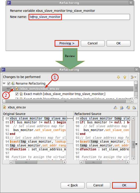
Figure 8: An IDE can automatically rename variables, modules, types, and other elements (AMIQ EDA).
Conclusion
The complexity of SystemVerilog and the diverse rules for design and verification code mean that different teams may take different approaches in their development process. Automatic refactoring by the IDE provides an effective way to convert all code to a common format adhering to a common set of rules. It also produces more compact code by eliminating redundancies, which makes code more readable and more maintainable. This saves both time and resources, one of the reasons why the IDE is a must-have for design and verification projects.
Further reading
This article is the fourth in a 12-part series providing a comprehensive and detailed analysis of the value and deployment of IDEs. You can access all the other parts by following the links below, presented in order of publication. You can also learn more about the Eclipse IDE from AMIQ EDA by following this link.
- Why hyperlinks are essential for HDL debugging
- A helping hand for design and verification
- Correct design and verification coding errors as you type
- Take advantage of the automated refactoring of design and verification code
- Delivering on the advanced refactoring of design and verification code
- Achieving the interactive development of low-power designs
- Accelerating the adoption of portable stimulus
- Accelerate your UVM adoption and usage with an IDE
- VHDL users also deserve efficient design and verification
- How IDEs enable the ‘shift left’ for VHDL
- Extract benefit from the automated refactoring of VHDL code
- e language users deserve IDE support too