Extract benefit from the automated refactoring of VHDL code
The evolution of languages for chip design and verification has been steady and significant over the last 40 years. Early proprietary hardware description languages (HDLs) introduced engineers to the idea that they could write code rather than draw schematics to create their designs. This ushered in an era of vastly increased efficiency: today a single engineer may be responsible for millions of gates, versus only a few thousand in the schematic days. VHDL introduced the concept of a standard HDL that could be supported by many tools from many vendors. The advent of logic synthesis was the final motivator to push virtually all digital design to coding in HDLs.
In more recent years, SystemVerilog has become the dominant hardware design and verification language, with SystemC and high-level synthesis starting to play an important role. However, VHDL remains the language of choice for many engineers. This is most common for FPGA-based designs, military and aerospace applications, and project teams in certain countries. VHDL users want to have access to all the tools and technology available to their SystemVerilog and SystemC colleagues since they share the same challenges.
One critical capability is the use of an integrated development environment (IDE) to create and modify designs and testbenches. Previous articles in this series have shown how the IDE can trace signals, traverse VHDL code, detect coding errors on the fly, suggest changes, and provide templates for new constructs. This article describes how the IDE can automatically refactor VHDL code for improved readability and maintainability, as well as better performance when consumed by simulation and synthesis tools.
Motivation for the IDE
Text editors, the traditional entry vehicle for all forms of code, have serious limitations when it comes to large projects with hundreds or thousands of source files. Viewing one file or even a few files at a time and navigating code with search commands does not scale. The seemingly simple act of tracing a variable across multiple files is tedious and prone to errors. Renaming a variable, function, or other element of the code is challenging because the change may have to be propagated across many files. Renaming a library element can touch every file. Only an IDE that ‘understands’ the source language (or languages) can handle these tasks in a user-friendly way.
Software programmers ran into these issues earlier than HDL coders, so IDEs became an essential part of their toolkits. As VHDL and Verilog became more popular and were used for ever larger projects, hardware design and verification engineers followed the lead of their software colleagues. IDEs for VHDL and other HDLs are available today. They provide deep language knowledge, sophisticated error-checking, and auto-correction suggestions. Tasks performed by the IDE include:
- Running on-the-fly syntactic and semantic checks, and suggesting fixes;
- Performing advanced static analysis;
- Simplifying code navigation using hyperlinks, semantic searches, and signal tracing;
- Providing visual representations like design schematics and state machine diagrams;
- Speeding up code writing using auto-complete and code templates;
- Highlighting and formatting the code; and
- Linking to a simulator for runtime debugging.
These capabilities provide ease of use and efficiency when entering and editing designs and testbenches, performing detailed code reviews, understanding inherited code, and debugging failing test cases during verification. Since few projects use only VHDL, the IDE can compile all design and verification languages, including SystemVerilog, Verilog, e, and C/C++. It is able to connect all elements together in a unified internal model of the complete design and verification environment. The IDE also provides a powerful and intuitive graphical user interface (GUI) for easy navigation and interactive debug. The right IDE can save engineer-years of effort and shorten a chip project schedule by months.
Refactoring VHDL code
The IDE provides a wide range of auto-correct options, as well as code completion suggestions and templates, based on its language knowledge and extensive error checks. In addition, it can ‘refactor’ VHDL code to improve how well it is handled by logic synthesis, compilers, and other tools as well as how easily it can be supported, debugged, and evolved by engineers. Refactoring is geared not toward finding or fixing bugs in the code, but instead toward improving comprehensibility and supportability. In practice, refactoring sometimes reveals bugs that were hidden in the ‘mess’ and become visible in better code.
Refactoring operations change the code without altering its black-box functionality. A VHDL front end for any design or verification tool should build the same internal model from the code before and after refactoring. For example, renaming elements in the code does not change the structure of the model. This common refactoring task sounds simple, but it can be painful when using a traditional text editor to write and modify code. Changing the name of an entity may involve edits to many files, and text editor searches may require tedious validation because of other elements in the code with similar or identical names.
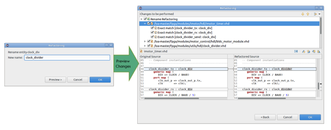
With the IDE, all refactoring operations are automated but entirely under the control of the user. Figure 1 shows how much better the process for renaming an entity works (please note that all figures in this article can be enlarged by clicking on the images as they appear in the text). The user selects the entity to be changed and types in the new name. The IDE shows all the files that will be affected by the renaming and the user can preview the proposed changes in each file. Upon approval, all relevant files are modified automatically, and the IDE’s internal database is updated. This screenshot and those that appear in the following examples are from the Design and Verification Tools (DVT) Eclipse IDE from AMIQ EDA.
The IDE allows users to easily rename many kinds of elements, including ports, types, functions, procedures, variables, and arguments. One of the most challenging renaming operations to perform manually is changing the name of a port that crosses multiple levels of design hierarchy. With the IDE, there is no need to search and edit in multiple files. The refactoring process makes the changes recursively both up and down the hierarchy. For every port, both the declaration and all its references are renamed. The user can preview the changes in the source files and in a schematic diagram, as shown in Figure 2.
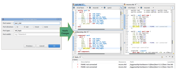
Several advanced automatic code manipulation operations are sometimes referred to as ‘refactoring’ in a broader sense, even if they do not strictly comply to the black-box equivalence stated earlier. It is easy to add a new port to an entity, for example, when expanding the design and adding new instances that need to be connected. In Figure 3, the user specifies the new port and previews the changes in the declaration and all instances of the entity. The signals to be connected are flagged with ‘FIXME’ as a reminder that the user must complete the task.
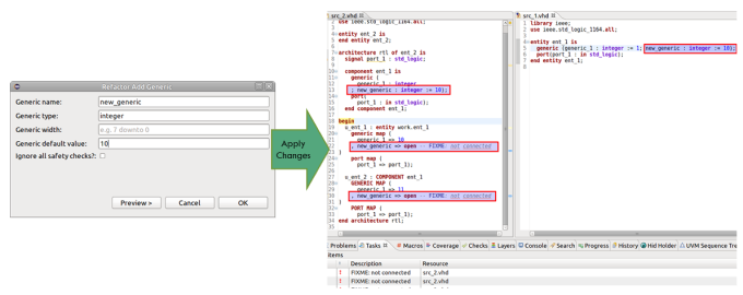
Similarly, it is easy and fast to add a new generic to an entity. As shown in Figure 4, the user selects the entity and invokes the Add Generic wizard to specify the name, type, width and default value of the new generic. The fields to be filled in by the user are flagged with ‘FIXME’ as a reminder to complete the specification.
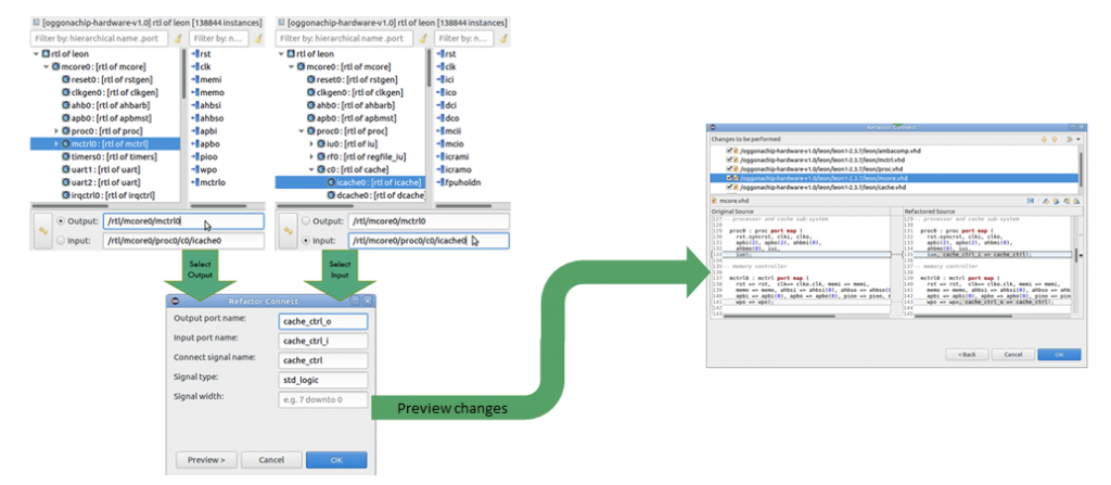
The IDE also automates the process of connecting two entity instances using ports just added or existing ports. As shown in Figure 5, the user selects the output instance (the signal source) and the input instance (the signal destination). New ports will be created up or down the design hierarchy as needed, in order to propagate the signal. As with all refactoring operations, the user can preview the changes to the code before approval.
The IDE can also make refactoring changes deep within the code even when there are no new ports or connections added. For example, an expression inside a subprogram, process, or protected type can be extracted to a local variable. This operation is shown in Figure 6, where the user has selected an expression and the IDE has created a new local variable. The user can change the name and type of the variable, and then choose whether to replace all occurrences of the expression or only the selected one.
Consistent alignment and indentation of code is also a type of refactoring. This may be considered the most basic form, but the value of such ‘pretty’ code formatting should not be underestimated. This makes the code easier to understand and maintain, especially when new engineers encounter it, or even when the original engineers revisit it after a prolonged period. Some basic code formatting operations include:
- Aligning vertically by selected tokens (such as colons and equal signs);
- Indenting designated constructs (such as ‘then’ keywords and parameters);
- Compacting whitespace that does not affect vertical alignment or indentation;
- Trimming whitespace from the end of lines;
- Mixing multiple tabs and spaces in whitespace as specified by the user;
- Adding whitespace before or after specified tokens;
- Wrapping lines that exceed a specified line width; and
- Wrapping multi-line comments to fit the line width.
Some companies allow individual engineers to choose their own formatting preferences; others require the use of a project-wide or company-wide configuration file so that all code looks consistent. Figure 7 shows an example of selected formatting rules applied to typical hand-entered VHDL. Scanning declarations, following the flow of nested conditional statements, and other aspects of code review are much easier with consistent formatting and vertical alignment.
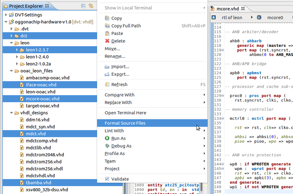
The IDE makes it easy to format multiple files in the same way to ensure consistency and to enforce coding guidelines. In Figure 8, the user has selected specific files of interest and directed that they be reformatted. The IDE notifies the user if any of the affected files are read-only and offers the chance to make then writable. If the user declines, these files are reported as not having been reformatted.
Conclusion
VHDL has had several revisions since its original standardization, and it is now a complex hardware design and verification language. VHDL users benefit greatly from the IDE, with its deep insight into the language and its easy-to-use GUI. Automatic refactoring provides an effective way to convert all code to meet a common set of rules. It also produces more efficient and more compact VHDL by eliminating redundancies, which makes code more readable and more maintainable. The IDE enables a significant ‘shift left’ in the design and verification process while saving critical project resources.
Further reading
This article is the eleventh in a 12-part series providing a comprehensive and detailed analysis of the value and deployment of IDEs. You can access all the other parts by following the links below, presented in order of publication. You can also learn more about the Eclipse IDE from AMIQ EDA by following this link.
- Why hyperlinks are essential for HDL debugging
- A helping hand for design and verification
- Correct design and verification coding errors as you type
- Take advantage of the automated refactoring of design and verification code
- Delivering on the advanced refactoring of design and verification code
- Achieving the interactive development of low-power designs
- Accelerating the adoption of portable stimulus
- Accelerate your UVM adoption and usage with an IDE
- VHDL users also deserve efficient design and verification
- How IDEs enable the ‘shift left’ for VHDL
- Extract benefit from the automated refactoring of VHDL code
- e language users deserve IDE support too
 Tom Anderson is a technical marketing consultant working with multiple EDA vendors, including Agnisys. His previous roles have included vice president of marketing at Breker Verification Systems, vice president of applications engineering at 0-In Design Automation, vice president of engineering at IP pioneer Virtual Chips, group director of product management at Cadence, and director of technical marketing at Synopsys.