Delivering on the advanced refactoring of design and verification code
Today’s system-on-chip (SoC) devices are incredibly large and complex even compared to chips developed only a few years ago. The largest designs have billions of transistors with massive capacity for IP blocks, memories, and programmable logic. Design and verification tools have had to evolve in major ways to handle this generation of devices. Languages have also evolved, with projects using a mix of SystemVerilog, Verilog, VHDL, e, and C/C++, plus various scripting languages.
One thing that has changed is that text editors, no matter how ‘smart’ they may claim to be, are not sufficient for creating and editing design and verification code. Some editors provide limited help, such as coloring code to identify language keywords and forms of auto-complete for some parts of the code. But editors deal with only one file at a time, and true assistance for HDL coding requires knowledge of the complete, compiled design and verification environment.
Assistance within the IDE
An integrated development environment (IDE) is a highly interactive tool that help engineers develop, test, and debug their code. First developed for software engineers, IDEs are now available to support both hardware designers and software engineers as they create and modify designs and verification testbenches. An IDE can support the full range of software programming languages, modeling languages, hardware description, and dedicated verification languages, including both the design and verification features of SystemVerilog.
An IDE can:
- Perform many types of checks on the code;
- Highlight and format the code according to user preferences;
- Compile the code to present the complete design and testbench structure;
- Connect to a simulator for debugging failing verification test cases; and
- Provide an intuitive graphical user interface (GUI) for code development.
In contrast to a text editor, an IDE compiles all design and verification source code and builds an internal database of the complete environment. This allows for easy tracing of signals and other analysis requiring full knowledge of the project code. With an IDE, engineers can navigate code more quickly, identify and fix a wide variety of coding errors, and even receive suggestions on making these fixes. When engineers are creating code, an IDE provides sophisticated auto-complete capabilities and templates for new code constructs.
An IDE can also perform refactoring, the process of restructuring code without creating new functionality. Refactoring makes code more readable and more maintainable, while often making it more efficient for simulation and synthesis tools. The simplest form of refactoring is consistent code alignment and indentation to conform to company or project guidelines. More sophisticated refactoring optimizes code and transforms between coding styles that perform the same function. This is especially important for SystemVerilog, a very large language with numerous overlapping constructs.
Users may also want to make modifications to the code that may change the design’s functionality, such as adding new signals. The advanced refactoring capabilities of an IDE can provide a good deal of assistance in these cases as well. Once the engineers have specified what they want to do, an IDE can make the required modifications and propagate the effects throughout the entire design hierarchy. This can save hours over making manual changes to multiple files in a text editor while being free of typos and errors introduced by the tedium of manual editing.
Examples of advanced refactoring
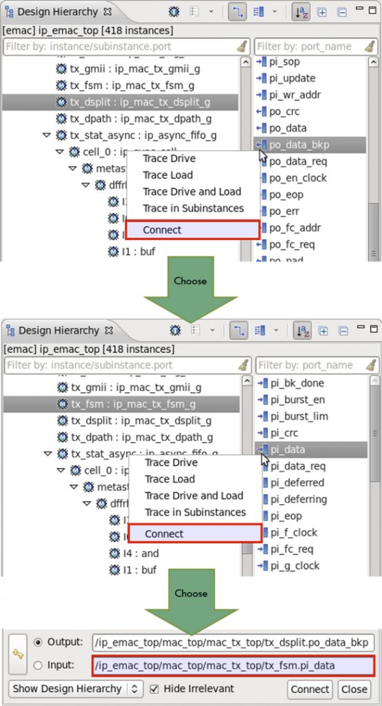
One common example of a code change that is hard to do manually is adding a new signal to connect two existing ports in the design hierarchy. As shown in Figure 1, this task is much easier with an IDE. The user first selects the module instance and then chooses the output port that will drive the new signal. Similarly, the user selects the module instance and port that will receive the new signal. If the two selected ports are at different points in the hierarchy, numerous instances at multiple levels may have to be modified to propagate the new signal. Here, the IDE takes care of this automatically and its use may save hours of manual editing. After naming the new signal, the user previews and approves before the IDE modifies the code and rebuilds the database automatically. This screenshot and the others that appear in the following examples are from the Design and Verification Tools (DVT) Eclipse IDE from AMIQ EDA.
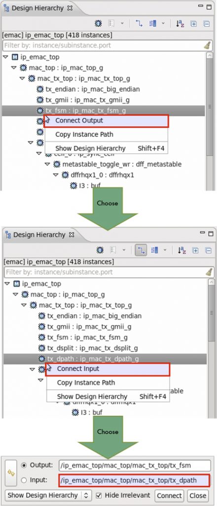
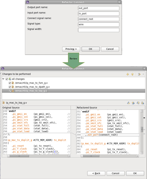
The process is very similar if the user wants to connect two module instances by adding new ports. As shown in Figure 2, the user selects the module instance to which the output port should be added and the instance to which the input port should be added. As shown in Figure 3, after having the opportunity to name the new ports and the connecting signal, the user can preview all modifications before the IDE makes them. Again, any instances up and down the hierarchy that also need changes are handled automatically.
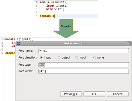
A user might wish to add a port to a module without connecting specific instances. Figure 4 shows a module declaration and the selection of an internal signal that will be converted to a port. The user can also select direction and other attributes and then the IDE adds the port automatically.
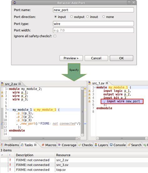
As shown in Figure 5, the IDE can also add an entirely new port to a module after the user has specified attributes such as name and direction.
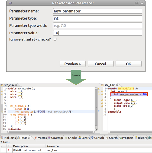
Adding a new port to a module declaration adds it to all instances of that module. Figure 5 also shows the IDE flagging the unconnected new ports on the instances and adding their eventual connection to a list of tasks for the user. The process of adding a new parameter to a module is very similar, as shown in Figure 6. Instances where the parameter must be added are flagged and required updates are highlighted as user tasks.
Refactoring scripts
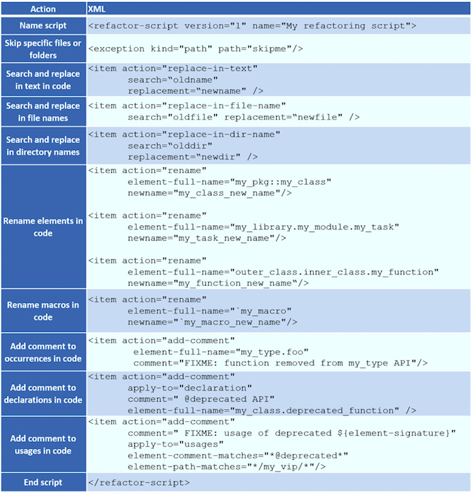
The GUI features of an IDE are ideal for all forms of interactive work, including refactoring. Users can experiment with different options, preview proposed changes, decide which refactoring operations they wish to apply, and update all relevant files. An IDE will instantly rebuild its internal model with the changes reflected. An IDE also supports repeated refactoring operations via a script. Refactoring scripts are XML files that describe a set of changes to be performed for a project in source code, scripts, or file/directory names. This automated process is very useful when porting code from a library to another or reusing code on a new project where some renaming is required. Table 1 shows examples of actions available in a refactoring script.
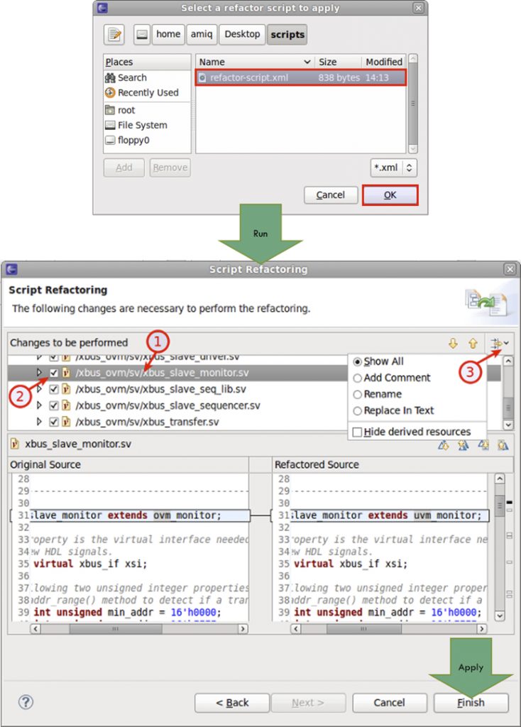
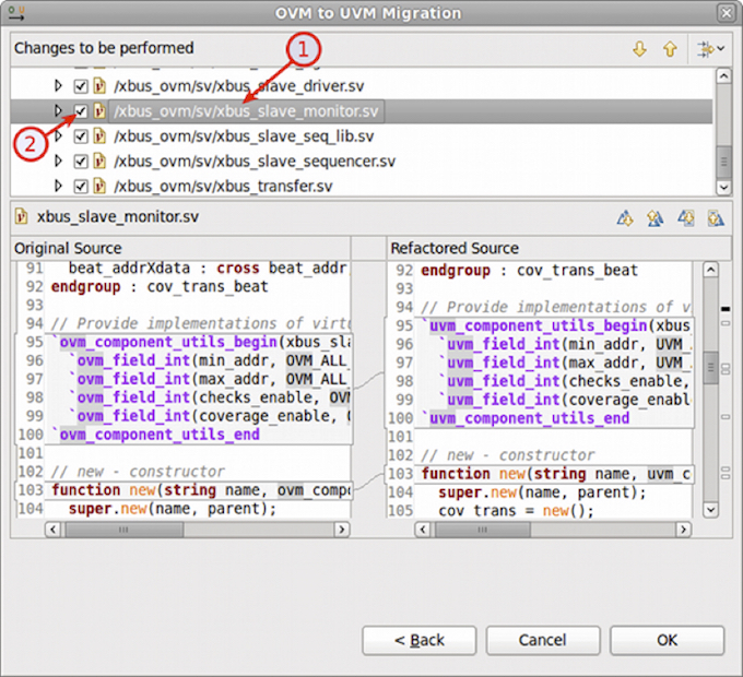
Once the refactoring script is created, the process of applying it within the IDE is straightforward. As shown in Figure 7, the user specifies the XML script file and runs it. The changes can be applied immediately, or inspected one by one to be applied or skipped (1 and 2). An option is available to filter the changes by the type of refactoring action (3). The selected changes are applied by clicking on the ‘Finish’ button.
One common example where a refactoring script is very helpful is migration from the legacy Open Verification Methodology (OVM) to the Universal Verification Methodology (UVM) standard. As a predecessor to the UVM, the OVM has many similarities, so it is possible to automate the conversion of code, file names, and directory names. In fact, the DVT Eclipse IDE includes a pre-built script that describes all the changes to be applied to a SystemVerilog source code base for migration from the OVM to the UVM. Figure 8 shows this script in use, with the option to filter, review, and selectively apply changes.
Conclusion
Modern chip designs, with hundreds or thousands of files, are almost impossible to code and maintain using traditional text editors. Even the most basic changes, such as adding signals, ports, and parameters, can have ripple effects that affect many design and verification files. Users can consume days or weeks of precious project time making tedious manual edits. Fortunately, an IDE can provide assistance. Given only the most minimal information from the user, an IDE can automatically make required modifications and propagate effects throughout the hierarchy. This saves time and money while making engineers more productive. An IDE is not a luxury, but a true necessity.
Further reading
This article is the fifth in a 12-part series providing a comprehensive and detailed analysis of the value and deployment of IDEs. You can access all the other parts by following the links below, presented in order of publication. You can also learn more about the Eclipse IDE from AMIQ EDA by following this link.
- Why hyperlinks are essential for HDL debugging
- A helping hand for design and verification
- Correct design and verification coding errors as you type
- Take advantage of the automated refactoring of design and verification code
- Delivering on the advanced refactoring of design and verification code
- Achieving the interactive development of low-power designs
- Accelerating the adoption of portable stimulus
- Accelerate your UVM adoption and usage with an IDE
- VHDL users also deserve efficient design and verification
- How IDEs enable the ‘shift left’ for VHDL
- Extract benefit from the automated refactoring of VHDL code
- e language users deserve IDE support too
 Tom Anderson is a technical marketing consultant working with multiple EDA vendors, including Agnisys. His previous roles have included vice president of marketing at Breker Verification Systems, vice president of applications engineering at 0-In Design Automation, vice president of engineering at IP pioneer Virtual Chips, group director of product management at Cadence, and director of technical marketing at Synopsys.