A helping hand for design and verification
In the world of high technology, there is often an interesting interplay between the most popular consumer products and the most advanced devices and algorithms. For example, the near-ubiquitous smartphone includes many highly complex hardware and software components to achieve its ease of use. Web browsers and search engines, even easier to use, rely on a wide range of sophisticated algorithms to get the job done. Successful consumer products insulate everyday users from the underlying complexity.
Sometimes it works the other way around: well-established concepts from the consumer world seep back to help with some of the more daunting engineering challenges. For example, design and verification engineers of deep-submicron chips need all the help they can get, and some of that help comes from such technologies as hyperlinks, auto-completion algorithms, and task-specific wizards. These familiar and powerful approaches are available to design and verification engineers as they write and debug code, but only if they move beyond traditional text editors.
From punch cards to text editors
It’s hard to imagine today, but less than 50 years ago the most common way to write a computer program was to punch cards, with each card containing a single line of code. Sad stories of programmers dropping large card decks and having to re-assemble them in the correct order were common. This time-consuming process was replaced by teletypes using a standard typewriter keyboard, with the ability to save and re-load programs saved on punched paper tape. It’s also hard to appreciate today how much of an advance this was at the time.
By the late 1970s, many computers provided cathode-ray-tube (CRT) displays showing what was being typed as well as the responses from running programs. The display technology has evolved to flat screens, tablets, and smartphones but the underlying mechanism has not. People see what they type and see program responses on some manner of screen. When typing a long sequence of characters, such as writing a document or coding a program, something better than tedious line-by-line entry was needed.
To meet this need, text editors were introduced. Typically, the editor would take over the entire display screen and allow the user to move about in the text, adding and deleting characters, and to search for strings of interest. Engineers writing designs in a hardware description language (HDL) such as Verilog or VHDL, or developing a testbench with SystemVerilog, e, or C/C++ reaped much benefit from text editors. For example, selectively renaming a variable could be performed by an automated query-replace operation rather than manual editing of multiple lines.
The sophistication of editors grew in several ways. The evolution from character-based to bit-mapped displays meant that editors could display multiple fonts, a much wider range of symbols, and multiple forms of highlighting. Touchscreens enabled cursor movement without using a mouse or key combinations. Some editors provided macros, extensibility in commands, and even some selective formatting and coloring of code based upon the syntax of the programming language being used.
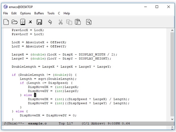
A single example demonstrates the sort of value that an efficient editing feature can provide. With an appropriate language extension, an editor can highlight the opening parenthesis, brace, or bracket when the closing symbol is entered. In Figure 1, the Emacs editor has highlighted the matching brace after the engineer has typed a closing brace three lines below. Especially in a complex equation with many parentheses or a deeply nested tree of if-then-else statements, this capability reduces many minutes of scanning code to a single second.
Knowing that such assistance is available with limited knowledge of a programming language’s syntax, engineers may wish for more capabilities. But this is where even the best text editor reaches its limitations. Many types of analysis require knowledge of how the design and the testbench are interconnected. This in turn means that the code base, often crossing hundreds or thousands of files, must be interpreted or compiled. Checks that span file boundaries or relate to the structure of the design and verification code demand a more capable solution.
IDEs to the rescue
Stepping beyond a text editor to an integrated development environment (IDE) provides a much wider range of capabilities. Code can be analyzed in context rather than as plain text, reflecting the structure of the specific language (or languages) being used. A typical IDE can accomplish a wide range of very useful tasks, including:
- Performing syntactic checks on the code;
- Performing static analysis checks on the code;
- Highlighting and formatting the code;
- Compiling or interpreting the code; and
- Connecting to a simulator for runtime debugging.
IDEs work equally well for programming languages, HDLs, dedicated verification languages such as e, and the verification-related features of SystemVerilog. The capabilities in the list above have clear value for entering and editing designs and testbenches, performing detailed code reviews, understanding a foreign design, and debugging failing test cases. Wrapping these capabilities with an intuitive graphical user interface (GUI) yields a solution that can shave many months off a schedule.
This level of insight requires powerful analysis engines backing the IDE’s GUI. A compiler must run behind the scenes continually, processing the source code every time the engineers make a change, and building an internal database of the design and the complete verification environment, including testbenches. This database must connect all design and verification elements, whether written in SystemVerilog, Verilog, VHDL, e, or even C/C++, allowing analysis crossing across source languages.
With this knowledge compiled and available, the IDE can perform a much broader range of analysis and even offer suggestions to the designers and verification engineers as they enter or debug their code. As mentioned earlier, these solutions are familiar since they echo features common in consumer-level software products. These include auto-correction and auto-completion in search engines, predictive typing in smartphones, and grammar and spelling checks in word-processing programs. All have corollaries in chip design and verification.
IDEs provide a helping hand with auto-complete
Perhaps the most common help that can be provided by the IDE is auto-completion of the name of an identifier that exists within the design or verification code. As an example, Figure 2 shows a partially entered function name, with the IDE presenting the two possible completions and allowing the user to choose. It also displays a description of the function taken from its definition. This screenshot and the others that appear in the following examples are from the Design and Verification Tools (DVT) Eclipse IDE from AMIQ EDA.
This feature is especially valuable for SystemVerilog, whose identifiers can represent signals, wires, modules, interfaces, macros, structures, variables, classes, tasks, functions, and more. In fact, the auto-complete options often depend upon the context and the type of identifier being entered. For example, when a dot is entered after an identifier, the IDE ‘understands’ that a member of a struct is being accessed and auto-completes accordingly. Figure 3 shows another example, with suggested completions based upon the specific values of an enumerated type.
Many SystemVerilog chip verification projects conform to the Universal Verification Methodology (UVM) standard. The IDE can have built-in knowledge of the UVM components, perhaps providing context-sensitive analysis and information. The UVM relies heavily on text macros that can be challenging to learn and use. As Figure 4 shows, the IDE can greatly simplify this process by offering auto-complete suggestions, each containing a detailed description and the list of arguments used by each macro.
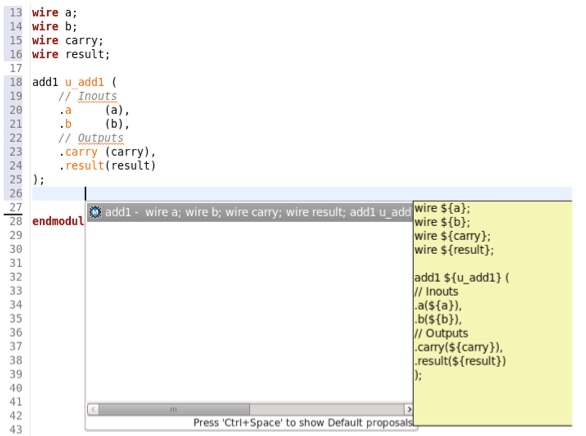
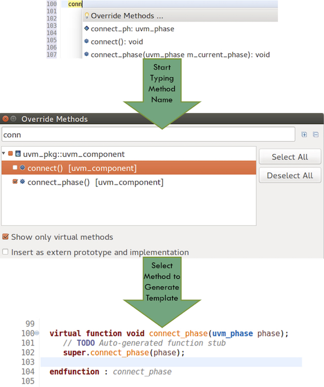
The IDE can go beyond displaying possible options to actively assisting engineers in hooking up a new component. In Figure 5, an instance of an existing module is being added to the code. The IDE is displaying all the identifiers that may need to be modified in order to connect the proper signals to the module inputs and outputs and to name the instantiated module. Similar functionality is available for functions, interfaces, and other structures. Figure 6 shows the use of autocompletion to override a method from a component’s parent class.
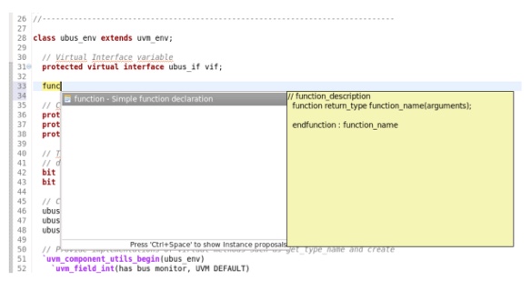
Auto-complete has clear value when designers and verification engineers want to reference existing identifiers. When defining a new element in the design or testbench, the IDE can also lend a helping hand by providing a code template for the engineers to fill in. Figure 7 shows a new function in the process of being defined along with a template showing the basic structure of SystemVerilog functions. Many engineers using text editors cut-and-paste code in this situation to ensure that they do not forget some detail; the IDE provides an automated, more efficient, and less error-prone solution.
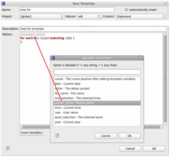
The IDE can provide a set of global code templates for popular design and verification languages, including SystemVerilog, VHDL, e, and C/C++. It should be possible to customize these templates on a per-company or per-project basis, or even to define entirely new code templates. An example of a custom definition appears in Figure 8. The information to be provided includes the template name, the template description, variables, and the context relevant to the template.
Conclusion
Design and verification engineers, like all computer users, have become used to tools that point out errors, have auto-complete features to fill in missing information when possible, and even offer suggestions to resolve issues. The IDE makes these same capabilities available during the demanding process of entering, verifying, and debugging semiconductor designs. The learning curve is minimal with an intuitive GUI, and the IDE provides efficiency benefits from its very first use. The IDE for design and verification is a required tool for any modern chip project.
Further reading
This article is the second in a 12-part series providing a comprehensive and detailed analysis of the value and deployment of IDEs. You can access all the other parts by following the links below, presented in order of publication. You can also learn more about the Eclipse IDE from AMIQ EDA by following this link.
- Why hyperlinks are essential for HDL debugging
- A helping hand for design and verification
- Correct design and verification coding errors as you type
- Take advantage of the automated refactoring of design and verification code
- Delivering on the advanced refactoring of design and verification code
- Achieving the interactive development of low-power designs
- Accelerating the adoption of portable stimulus
- Accelerate your UVM adoption and usage with an IDE
- VHDL users also deserve efficient design and verification
- How IDEs enable the ‘shift left’ for VHDL
- Extract benefit from the automated refactoring of VHDL code
- e language users deserve IDE support too
 Tom Anderson is a technical marketing consultant working with multiple EDA vendors, including Agnisys. His previous roles have included vice president of marketing at Breker Verification Systems, vice president of applications engineering at 0-In Design Automation, vice president of engineering at IP pioneer Virtual Chips, group director of product management at Cadence, and director of technical marketing at Synopsys.