Why hyperlinks are essential for HDL debugging
Surfing the World Wide Web is one of the easiest tasks engineers do every day; debugging their designs and testbenches is one of the hardest. EDA has been struggling for years to build tools that make debug tractable. Recent advances have borrowed ease-of-use aspects from popular computer applications such as Web browsers and applied them to some of the most complex design and verification problems. Hyperlinks turn out to be a key technology here.
The limitations of text editors
Since the widespread adoption of logic synthesis in the early 1990s, designers have used hardware description languages (HDLs) such as Verilog and VHDL. HDLs also contained constructs for verification, and these features were enhanced over time. Designers and verification engineers can thus capture a complete environment in code form, and often use traditional text editors to enter and modify HDL descriptions. This presents challenges even for such simple tasks as navigating code and tracing signals.
Within a single file, engineers can use the ‘search’ or ‘find’ function in their preferred text editor to find all occurrences of a given signal name. They copy the name from the HDL code into the search field and then the text editor steps through each match. Engineers can find out where a signal is defined, or which inputs and outputs are connected to the signal. But this ‘simple’ solution breaks down quickly.
Designs and verification environments are no longer contained in a single HDL text file, but spread across hundreds or thousands of files. There are good reasons for this, including partitioning the code across multiple engineers and enabling reuse. Adding design and verification libraries and IP from internal and external sources adds even more to the file list. Engineers trying to review or debug a design are faced with the challenge of finding which files contain a signal of interest.
Most EDA tools run on Unix-based operating systems, and the family of ‘grep’ utilities is the most common way to find a text string in a collection of files. Engineers can copy the name of the signal of interest, paste it into a grep command, and see which files contain that name. As each file is opened in a text editor, the name can be copied into the search field and located the same way as in a single-file design. Clearly, this is not an efficient method, but it is still used today by engineers relying only on simple text editors for their HDL code.
The case for IDEs
Stepping beyond a traditional editor to an integrated development environment (IDE) delivers a huge range of capabilities for design and verification engineers. The IDE is tuned to the specific language (or languages) being used, so the code is analyzed in context rather than as plain text. A typical IDE can accomplish a wide range of very useful tasks, including:
- Performing syntactic checks on the code;
- Performing static analysis checks on the code;
- Highlighting and formatting the code;
- Compiling or interpreting the code; and
- Linking to a simulator for runtime debugging.
Although IDEs were originally developed for software programming languages, they work equally well for HDLs, dedicated verification languages such as e, and the verification-related features of SystemVerilog. The capabilities in the list above have clear value for entering and editing designs and testbenches, performing detailed code reviews, understanding a foreign design, and debugging failing test cases. Wrapping these capabilities with an intuitive graphical user interface (GUI) helps compose a solution that can shave many months off a schedule.
One specific problem that an HDL IDE can address well is tracing a signal through a design split across many files. It is no longer necessary for engineers to grep for a signal name in the file list and then search for the name within each file returned. Engineers need no longer worry about partial name matches or identical signal names used in different design scopes. The IDE analyzes the entire design and ‘knows’ every connection to every signal. Signals can be automatically traced through any number of files and multiple levels of design hierarchy.
This level of insight requires powerful analysis engines backing the IDE’s GUI. A compiler must run behind the scenes at all times, quickly processing the source code every time the engineer makes a change and updating the internal database of both the design and testbench. This database must connect all design and verification elements, be they written in SystemVerilog, Verilog, VHDL, e, and/or even C/C++, thereby allowing analysis and signal tracing that crosses source code languages.
Hyperlinks bring the results of this analysis and tracing directly to design and verification engineers. The concept of hyperlinks has been around for more than 50 years, but their use exploded with the introduction of Web browsers in the mid-1990s. Clicking on a link that would ‘just do the right thing’ has become second nature to everyone. It has therefore become entirely natural and logical to extend the use of hyperlinks to the IDE used for capturing, verifying, and debugging HDL designs.
The efficiency and value of hyperlinks
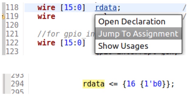
Figure 1 shows an example that uses a hyperlink to trace a signal within a SystemVerilog design or testbench. By hovering the mouse over a signal name while holding down the ‘Ctrl’ key, the name becomes a hyperlink. The user can choose to open the signal’s declaration, jump to the next signal assignment, or show all usages of the signal. This screenshot and those in the following examples are from the Design and Verification Tools (DVT) Eclipse IDE from AMIQ EDA.
This type of hyperlink speeds up design exploration and debug in several ways. The grep-search cycle required with simple text editors is obviated. Assignments to and usages of the signal are determined by the tool, so engineers do not have to differentiate manually between inputs, outputs, or left-hand/right-hand locations. The IDE is not confused if an unrelated part of the design also has an ‘rdata’ signal in a different scope. Clicking a hyperlink is instantaneous. Each step in tracing a signal is significantly reduced from many minutes of annoying scrolling through irrelevant grep matches to a few seconds.
This first example makes a compelling case for IDEs with hyperlinks but barely scratches the surface of what is possible. Modern languages, such as SystemVerilog, are incredibly complex. Identifiers may be simple signals or wires, but can also be modules, interfaces, macros, structures, fields, classes, tasks, functions, and more. Not every engineer is an expert at object-oriented programming. A sophisticated IDE can do a lot to aid in understanding and debugging a design and testbench.
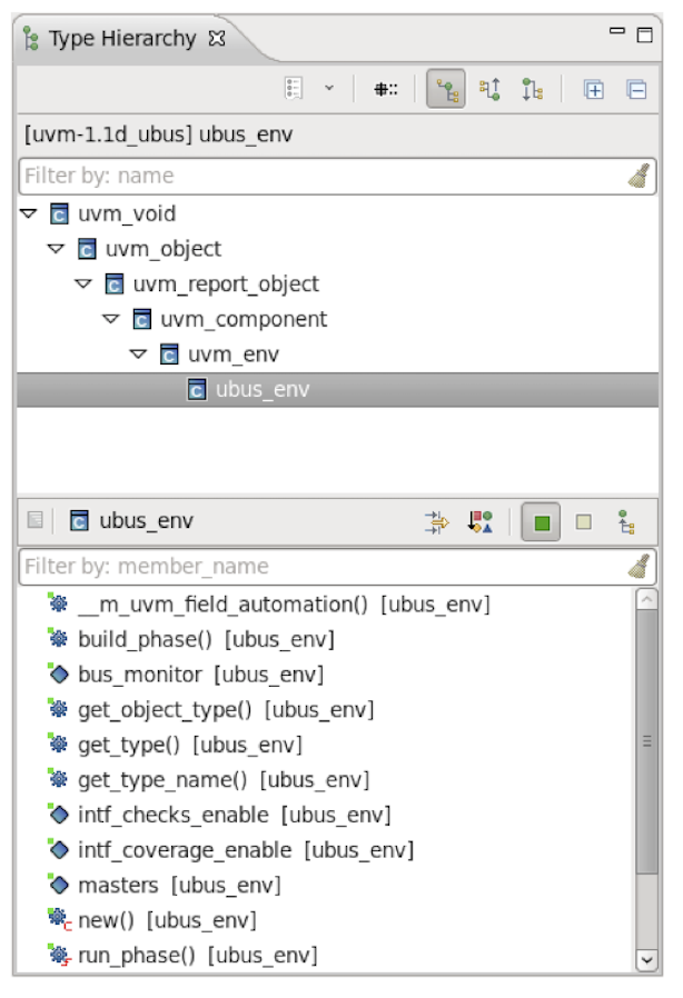
If the hyperlinked identifier is a class, then the IDE can display the entire class inheritance tree and the class members (Figure 2). This example is part of a SystemVerilog testbench compliant with the Universal Verification Methodology (UVM) standard. An IDE can have built-in knowledge of UVM, perhaps with special analysis and display/highlighting for standard components.
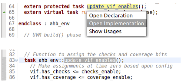
As another example, suppose that the identifier is a task that is implemented outside the class in which it appears. In this case, a hyperlink opens the task implementation wherever it appears. Figure 3 shows how this works. The traditional process of grepping and searching is again replaced by a single click on a hyperlink in the IDE. The ability to jump directly to definition or usage applies to any of the many SystemVerilog identifier types, providing a consistent and easy-to-learn interface.
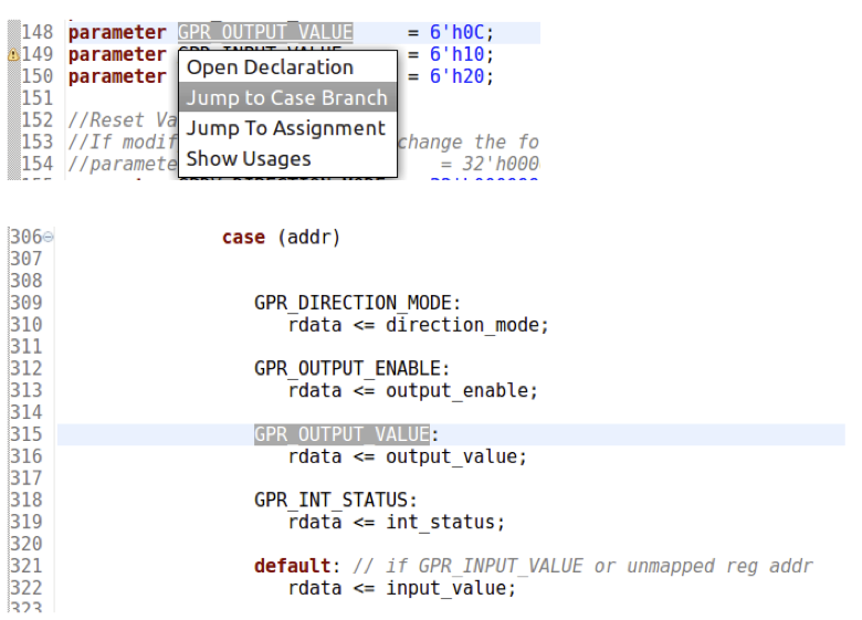
Figure 4 shows a code snippet in which the identifier is a parameter that is used as an expression in a case statement. The hyperlink jumps to the branch of the case statement that will be selected for that parameter. This approach only works with enumerated constants and parameters, so this is a good example of a construct-specific capability. Hyperlink options are specially tuned for specific constructs in the chosen language, in this case SystemVerilog. Other types of constructs may generate hierarchy trees, diagrams, schematics, and so on.
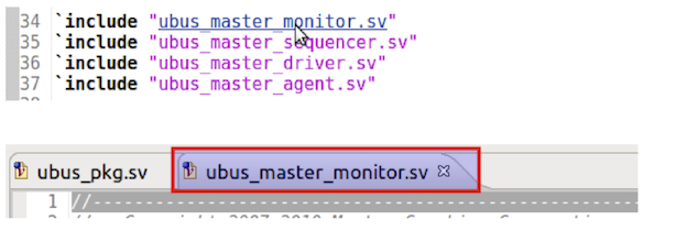
The IDE analyzes the entire file list that a simulator would read, as well as all simulation options and arguments that affect interpretation of the code. These include the traditional pre-processor directives, some of which are almost universally used. For example, the ‘include’ directive tells the pre-compiler to insert the contents a file at that point. Figure 5 shows how the name of an included file can hyperlink directly to the contents of that file. This step saves copying and pasting a file name into an editor’s ‘open file’ command.
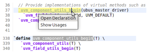
The ‘define’ pre-processor construct is also widely used, especially to define text macros. As shown in Figure 6, the IDE can jump to the definition of the macro and even expand it level by level. One of the most common complaints about UVM is its heavy reliance on SystemVerilog macros. As in the previous examples, the ability of the IDE to hyperlink the construct in question and ‘just do the right thing’ bypasses some of the complexity of SystemVerilog and reduces the UVM learning curve.
Conclusion
Debugging a large semiconductor design and its complex testbench is a major challenge; even perusing the code and trying to understand what it does is hard. Juggling printouts or using simple text editors is no longer an acceptable approach. Design and verification engineers need a modern IDE that performs sophisticated analysis and uses smart hyperlinks to navigate the code within a flexible GUI. Engineers and their managers must evaluate the options in the EDA market, choosing a solution rich in capabilities and proven on many previous projects.
Further reading
This article is the first in a 12-part series providing a comprehensive and detailed analysis of the value and deployment of IDEs. You can access all the other parts by following the links below, presented in order of publication. You can also learn more about the Eclipse IDE from AMIQ EDA by following this link.
- Why hyperlinks are essential for HDL debugging
- A helping hand for design and verification
- Correct design and verification coding errors as you type
- Take advantage of the automated refactoring of design and verification code
- Delivering on the advanced refactoring of design and verification code
- Achieving the interactive development of low-power designs
- Accelerating the adoption of portable stimulus
- Accelerate your UVM adoption and usage with an IDE
- VHDL users also deserve efficient design and verification
- How IDEs enable the ‘shift left’ for VHDL
- Extract benefit from the automated refactoring of VHDL code
- e language users deserve IDE support too
 Tom Anderson is a technical marketing consultant working with multiple EDA vendors, including Agnisys. His previous roles have included vice president of marketing at Breker Verification Systems, vice president of applications engineering at 0-In Design Automation, vice president of engineering at IP pioneer Virtual Chips, group director of product management at Cadence, and director of technical marketing at Synopsys.