Accelerating the adoption of portable stimulus
One of the hottest topics in semiconductor verification is the emerging technology of portable stimulus. Several EDA vendors have already developed related tools, and worked with the Accellera Systems Initiative to define a standard input format for them. Version 1.0 of the Portable Stimulus Standard (PSS) was released in June 2018, greatly increasing interest in this approach. Now that all the relevant commercial tools support the standard, adoption is accelerating.
However, embracing and applying the PSS on real chip designs is not trivial. PSS offers two input formats, both of which can be considerably more abstract than traditional SystemVerilog constrained-random testbenches. The impressive capabilities of the portable stimulus approach are driven by a rich set of constructs in the input formats. The learning curve can be significant, and even expert users may have to consult the standard from time to time. This article shows how to address these challenges and accelerate PSS adoption.
Background on portable stimulus
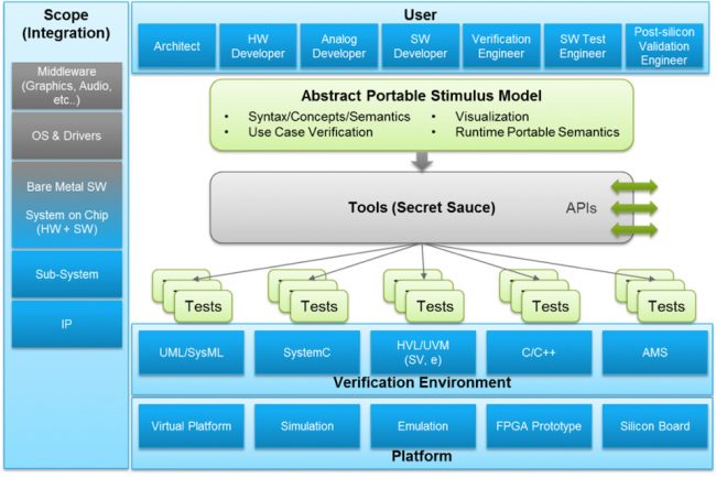
The vision of portable stimulus is clear: to find a way to write tests that can be portable ‘vertically’ from IP block to subsystem to system, and ‘horizontally’ from simulation to emulation to silicon. This vision is captured well in Figure 1, a diagram developed by Accellera in the early days of forming the Portable Stimulus Working Group (PSWG). As the diagram shows, the idea is to define an abstract model from which EDA tools can generate the tests appropriate for each level of design hierarchy and each verification platform.
Figure 1 The scope of portable stimulus ranges over many targets and user types (Accellera)
The term ‘portable stimulus’ is misleading, since stimulus cannot be portable across platforms. In simulation, stimulus is usually provided by a testbench, which does not even exist for in-circuit emulation and fabricated chips in the bring-up lab. Likewise, the tests are not portable since providing stimulus and checking results are performed in different ways on different platforms. Importantly, portable stimulus also includes the notion of verifying a chip by running tests on its embedded processors.
Portability actually resides in the abstract model, and so commercial EDA tools deliver their differentiating value by generating tests tuned for the different targets. For example, simulation tests might be short with frequent input and output activity, while in-chip embedded tests are likely to run a long time with minimal pin activity. The PSWG was established to define the format for abstract PSS-compliant models, with chip verification teams defining their needs and EDA vendors developing proof-of-concept tools to ensure that it was possible to generate tests efficiently from the resultant models.
As Figure 1 shows, the PSS was intended to serve a wide range of users, from system architects to post-silicon validation teams. The experiences and needs of these users vary considerably, so it proved impossible to create one format to serve everyone. The PSS defines two semantically equivalent formats, a SystemVerilog-influenced domain-specific language (DSL) and a C++ class library. The expectation was that verification engineers would choose the former, while system architects and embedded programmers would choose the latter. This article focuses on PSS DSL because it has a unique syntax and semantics.
There is no doubt that the PSS is very powerful, with impressive case studies and growing adoption. There is also no denying that it is complex; the current 1.0a release document is 319 pages. This complexity can be daunting to chip teams looking to use the standard on real projects. But modern chip design and verification tasks involve numerous languages and formats, and integrated development environments (IDEs) can reduce learning times and save effort even for experienced users. It stands to reason that an IDE for the PSS would deliver similar benefits.
The value of an IDE
The IDE is well established as a way to ease the adoption and use of complex languages. Originally developed to aid software programmers, IDEs are now available for hardware designers and verification engineers. Support is available for SystemVerilog, Verilog, VHDL, e, C/C++/SystemC, and the UPF and CPF power-intent formats. Engineers can develop, test, and debug their code interactively, while managing complex projects with thousands of design and testbench files. Among its many capabilities, an IDE can:
- Perform many types of checks on the code;
- Highlight and format the code according to user preferences;
- Compile the code to present the complete design and testbench structure;
- Connect to a simulator for debugging failing verification test cases; and
- Provide an intuitive graphical user interface for code development.
Because the IDE compiles all the design and verification source code, it can build an internal database of the complete environment. The knowledge encapsulated in this database enables features far beyond those of traditional text editors. The IDE can traverse deep design and testbench hierarchies, suggest possible fixes for coding errors, refactor code to be more efficient and maintainable, auto-complete partial inputs, and provide templates for adding new code. These features are as valuable for PSS DSL models as for any other language.
Interactive PSS development and debug
PSS DSL can be regarded as just another language for chip design and verification. While it enables modeling at a higher level of abstraction than most other languages, it benefits from IDE support in much the same way. The internal model compiled by the IDE includes the PSS information, so all applicable checks and features can be applied. These include navigating through the design, detecting errors, suggesting fixes, auto-completion, coding templates, and refactoring code.
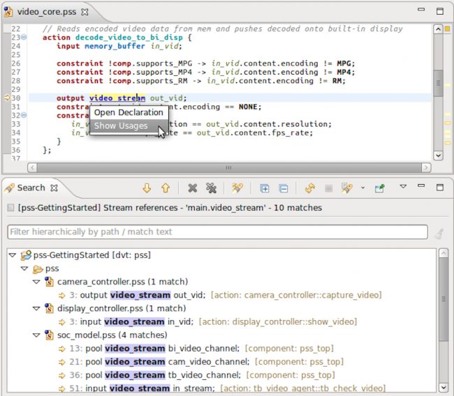
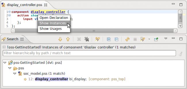
PSS models may be quite large, with deep hierarchies and many repeated instances. As with any large model, navigation can be a challenge. Clicking through hundreds of files and searching with a text editor is tedious. Since the IDE has the entire design and testbench compiled, it is easy to trace all interconnections. Users can click on any signal and jump to its definition, source, and destinations. Similarly, it is easy to toggle between the definition and usages of a method, field, struct, action, or any other PSS element. Figure 2 has an example of this. Similarly, Figure 3 shows the IDE displaying all instantiations of a PSS component. These screenshots and the following examples are from the Design and Verification Tools (DVT) Eclipse IDE from AMIQ EDA.
Figure 2 The IDE can trace a PSS stream and find all its usages (AMIQ EDA)
Figure 3 The IDE can search and display all instances of a component (AMIQ EDA)
When the IDE compiles and analyzes the PSS model, syntax errors in language constructs, many types of semantic errors, and uses of undeclared identifier names are flagged. In many cases, a possible fix is suggested, as shown in Figure 4. Figure 5 demonstrates that these capabilities even extend to checking for spelling errors in comments.
Figure 4 The IDE can detect a naming error and suggest a fix (AMIQ EDA)
Figure 5 The IDE can find a spelling error and suggest a fix (AMIQ EDA)
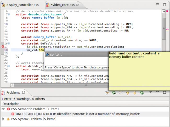
When the user is typing in new DSL code, the IDE offers considerable assistance. Both language constructs and identifiers in the model can be auto-completed, making errors much less likely. In Figure 6, the user has typed in a partial name and the IDE has provided an auto-completion for approval. The user then moves on to edit a constraint that happens to be an enumerated type. The IDE recognizes this, and offers a choice of the available enumerated values for auto-completion.
Figure 6 The IDE can auto-complete partial names (AMIQ EDA)
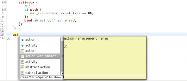
Sometimes, more information is required from the user than can be provided by choosing from a list of auto-completion options. In these cases, the IDE provides a coding template showing the fields that must be completed. In Figure 7, the selected option requires specification of an action name and a parent name. Coding templates greatly reduce the time spent consulting the PSS standard for the details of how to code unfamiliar constructs.
Figure 7 The IDE provides coding templates for PSS constructs (AMIQ EDA)
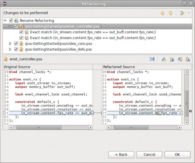
The IDE can also refactor PSS code, that is, modify code without changing its functionality, including by formatting it to fit coding guidelines, and renaming elements. In Figure 8, the IDE is assisting the user in renaming a variable. This is automated because of the internal model and the ease of finding all references without having to use search in a text editor.
Figure 8 The IDE can rename all occurrences of any PSS element (AMIQ EDA)
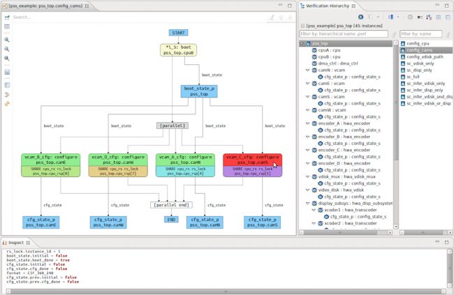
Perhaps the most advanced PSS-related feature of the IDE is scenario generation and visualization. Dedicated EDA tools use the PSS model to generate tests for particular design levels, verification platforms, and users in Figure 1. These tests must satisfy the abstract PSS specification, which entails ‘solving’ the model to meet its constraints and other rules. The IDE does not generate tests, but it can analyze the PSS model and display scenarios that satisfy the abstract specification. Figure 9 shows one solution, including a graphical view of the actions performed in the scenario.
Figure 9 The IDE can display possible scenarios that satisfy the PSS model (AMIQ EDA)
This is a valuable feature since a huge number of valid scenarios can be generated from the single PSS model. That’s one indication of the power of the portable stimulus abstraction. However, it can be hard for an engineer writing or maintaining a model to visualize the details of the possible scenarios. There may be multiple ways to solve the model to generate valid scenarios, some of which may not be obvious (or even intended). Further, there are almost always many parallel activities possible in the model. Visualization of complete, detailed scenarios helps the engineer determine whether the PSS model is correct. If the IDE cannot generate a valid scenario, it provides detailed debug information to help the user fix the PSS model.
Conclusion
Traditional chip pre-silicon verification and post-silicon validation has required multiple teams coding in different languages, often having to re-create similar tests at multiple stages of the project. The portable stimulus vision of generating tests throughout the project from the same abstract model was developed to address this challenge. Following the release of the Accellera PSS, there are now compliant tools available from multiple EDA vendors. While not yet mainstream, adoption is growing quickly. An IDE makes learning the DSL much easier and saves time in common operations, even for experts. An IDE is an essential part of adopting and deploying the PSS.
Further reading
This article is the seventh in a 12-part series providing a comprehensive and detailed analysis of the value and deployment of IDEs. You can access all the other parts by following the links below, presented in order of publication. You can also learn more about the Eclipse IDE from AMIQ EDA by following this link.
- Why hyperlinks are essential for HDL debugging
- A helping hand for design and verification
- Correct design and verification coding errors as you type
- Take advantage of the automated refactoring of design and verification code
- Delivering on the advanced refactoring of design and verification code
- Achieving the interactive development of low-power designs
- Accelerating the adoption of portable stimulus
- Accelerate your UVM adoption and usage with an IDE
- VHDL users also deserve efficient design and verification
- How IDEs enable the ‘shift left’ for VHDL
- Extract benefit from the automated refactoring of VHDL code
- e language users deserve IDE support too
 Tom Anderson is a technical marketing consultant working with multiple EDA vendors, including Agnisys. His previous roles have included vice president of marketing at Breker Verification Systems, vice president of applications engineering at 0-In Design Automation, vice president of engineering at IP pioneer Virtual Chips, group director of product management at Cadence, and director of technical marketing at Synopsys.