Automating wire-harness development
The electrical wiring harness inside a vehicle is taking on greater significance as more functions are put under the control of electronic control units (ECUs) distributed around the car. The trend not only increases the number of signals that need to be passed by the harness but the complexity of the harness structure. Not only does each harness have to cope with a wide variety of network, sensor, and power connections, the many customizations that can be applied to a manufactured vehicle lead to countless configurations that need to be supported and tracked.
Today, though, wire-harness manufacture remains a labor-intensive process: according to John Judkins and Sven Neeser of Mentor, a Siemen business, writing in a recently released white paper some 85 percent of wire-harness constructions processes are carried out by hand, leading to a high potential for error that will only be detected during final assembly. A further problem is the fragmentation of design and manufacture. Design data often needs to be transferred manually to the appropriate manufacturing functions. This, inevitably, leads to delays and mistakes being made, particularly during the high-pressure new-production introduction phase. Another problem for companies as they evolve is the handling of “tribal knowledge” – the information about processes and techniques that employees know but which is never fully documented.
The white paper authors describe a typical, high-level manufacturing engineering flow in the wire harness industry:
“First, design engineering releases initial designs or engineering changes for costing and providing quotes to the customer. Next, the main formboard is designed, followed by production modules and sub-assemblies, which sometimes require their own assembly board. Next, the engineers will design a bill of process (BOP) for the entire harness, allocating wires, splices, twisted wires, and all remaining material to its designated equipment or work station. The BOP is then released into the enterprise resource planning (ERP) system. This is followed by balancing and optimization of the final assembly carousel and then creation of the work instructions.”
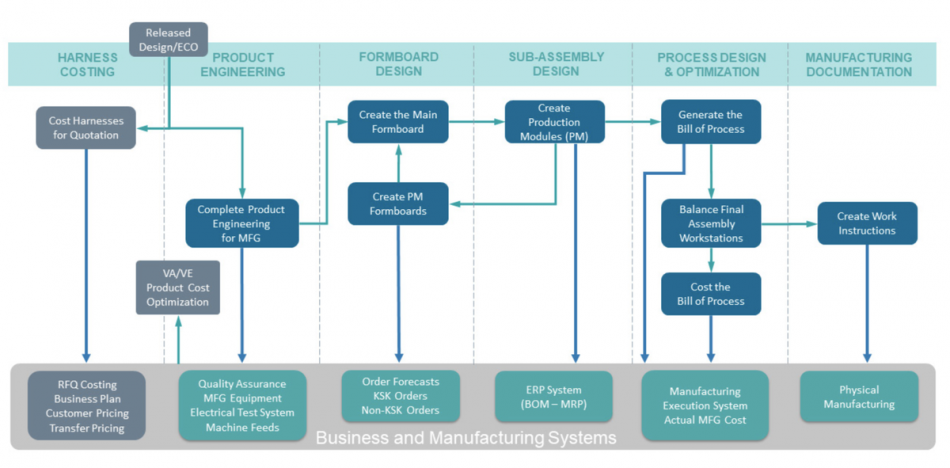
Image Typical high-level harness manufacturing flow
Errors from data re-entry and translation can lead to errors that take time and effort to rectify. The white-paper authors recommend in its place a model-based engineering (MBE) approach.
“In a digital world, companies create a digital thread in which all of the functions, from architectural and functional design through to physical design, manufacturing engineering and after-sales service, can all use the same data. At each stage of the harness lifecycle, each stakeholder can use the same data models and have access to decisions that are made in other domains.”
With the aid of this digital thread, it becomes possible to support the many manual and automated processes that are used in wire-harness manufacturing and assembly. For example, ERP systems more readily help manage material stores with manufacturing execution systems (MES) employed to supply workbooks to shopfloor staff and gather real-time data to help improve the processes over time. The authors claim: “A model-based engineering approach, with a continuous digital thread, can help harness manufacturers reduce design errors by 50 percent, quote-to-production cycle time by 30 percent, and formboard design time by up to 85 percent.”