Focus your use of Portable Stimulus on three key axes
Portable Stimulus allows reuse along horizontal, vertical and technique axes, but you need to be aware of the strengths and weaknesses of each to get the greatest benefits.
Once upon a time, discrete units — transistor, IC, IP — were the talk of the town, the focus of our attention. Now, although these seemingly quaint characters continue to be impressive and essential in their own right, they have become supporting players on a much bigger stages: the system, the system-of-systems, even electrical-mechanical-environmental systems.
Tools and solutions must not only perform on each of these stages. They must also be able to move as freely as possible from one to the other. We have a long way to go, but in the realm of digital verification, the Accellera Portable Stimulus Specification (PSS) standard is a very good start, fulfilling the need to automate the generation of quality stimulus across the verification spectrum.
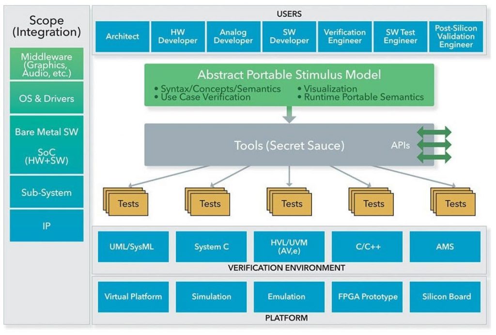
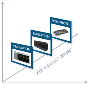
Portable Stimulus makes it easy to customize the rules under which a description operates without modifying the original source code, thereby also making it easy to customize the behavior of test intent based on the specific constraints of the environment in which the test is currently operating. The PSS language supports capturing test scenarios in such a way that they are reusable across different verification levels (block, subsystem, and SoC) and execution environments (simulation, emulation, and prototype), as illustrated in Figure 1.
But how do you get started? This article looks at the organizational implications of adopting portable stimulus. It describes three axes of reuse for identifying the focal points for reuse in your applications.
- Vertical Reuse: Reuse of test intent from the block to subsystem to SoC levels of verification
- Horizontal Reuse: Reuse of test intent across derivatives of the same design or across designs with significant similarities
- Technique Reuse: Reuse of automated stimulus techniques in environments that do not have good automated stimulus
By understanding these three axes and designating a focal point for adoption, you will be able to identify the resources you need and the gaps you may have between your existing infrastructure and what is required to take full advantage of Portable Stimulus.
Reuse along these axes has different characteristics in terms of the upfront work that must be done to enable each one, and the benefits that are achieved by doing so. While many applications include aspects of two or more axes of reuse, most applications will have a primary focus on one.
Let’s look at the three axes of reuse in detail so you can precisely identify which is right for your project and make the best use of Portable Stimulus the first time you use it and every time thereafter.
Vertical Reuse axis
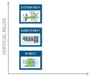
Vertical reuse (Figure 2) is what often comes to mind when we think of portable stimulus: Reuse of test intent from the block to system level. Test intent is developed during verification of an IP block, then reused when verifying a subsystem in which that IP is used, and then either reused on its own, or in conjunction with subsystem-level test intent, at the SoC level.
The IP Block Level
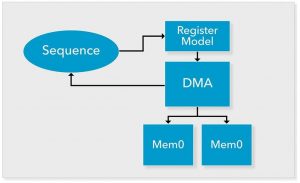
At the IP block level, we use a UVM testbench environment to verify the IP’s operation (we use a DMA in the example shown in Figure 3). UVM helps us carry out transaction-oriented verification. So, for example, we might create a UVM sequence item to describe a DMA transfer on a single DMA channel, and a UVM sequence to exercise the DMA engine with a series of these DMA-transfer transactions.
PSS helps us move our verification test intent up to the scenario level. With PSS, we characterize the key operations that a block can perform, and the rules about how those operations must be carried out.
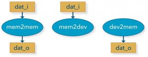
For our DMA engine, we might describe three key operations that the DMA can carry out: Transfer from memory to memory; transfer from memory to a peripheral device; and transfer from a peripheral device to memory (Figure 4). In PSS, we create a new PSS action to describe each operation. For each of these actions, we characterize the data that the operation requires (if any) and the data (if any) that it produces.
Our memory-to-memory transfer action needs to know where the source data is. This is modeled as an input (dat_i) to the action. The memory-to-memory transfer action transfers data to a destination location. We model this as an output (dat_o) so that other actions can input this information. PSS provides us many features in addition to action inputs and actions that help us model the way our actions can execute and how they can legally be combined into a scenario.
The scenario-level modeling that PSS provides is useful at the block level. For example, each of our DMA actions requires access to a dedicated DMA channel because only one transfer at a time can run on each channel.
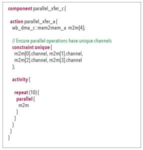
Creating a scenario that runs four parallel transfers on four randomly-selected by unique DMA channels is as simple as the code shown below. We create an array of memory-to-memory transfer actions, add a constraint to ensure that the channel used by each is unique, then execute all four actions inside a ‘parallel’ block to cause all transfers to execute simultaneously. This ability to model test intent at a higher level of abstraction makes users more productive and allows the creation of more-complex tests even at the block level. However, the reuse benefits of modeling test intent using actions and scenario rules becomes even more apparent at the subsystem level.
Subsystem Level
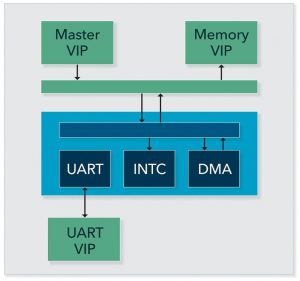
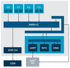
Continuing with our PSS IP to SoC reuse example, we move up to the subsystem level. The subsystem shown in Figure 5 contains the DMA engine we looked at in the previous section, but now also a UART. Since our goal is to reuse test intent from IP to SoC, we will have created PSS actions to describe the configuration, transmit, and receive operations that we can perform on the UART.
Reusing test intent created at the block level allows us to create subsystem-level test scenarios to ensure that our IP are correctly integrated in the subsystem. Now, of course, our PSS test intent for each of the IPs was not created with a specific subsystem in mind. Consequently, we will need to customize it to reuse it at the subsystem level. Fortunately, PSS allows us to extend existing actions, components, and data structures to add new constraints without actually modifying the original code.
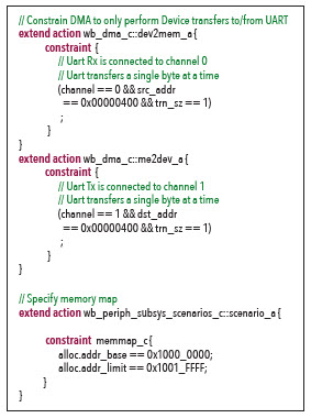
The code below shows how we customize the operation of the DMA actions to make them work in our subsystem. Our memory-to-memory transfer action does not require any specific customization. As long as we configure memory addresses correctly, the memory-to-memory transfer action will work in any system. The device-to-memory transfer and memory-to-device transfer actions are a different story. These actions must work with a specific IP connected to one of the handshake interfaces on the DMA. Our block-level testbench allowed any DMA channel to use handshake-transfer mode, but our subsystem only uses two of the handshake interfaces, and connects them to the UART IP.
The ‘mem2dev’ and ‘dev2mem’ actions are also customized in this code to force them to work only with the UART. The UART’s receive-handshake signals are connected to the DMA’s channel 0, so we extend the ‘dev2mem’ action such that it only works with channel 0 and always uses the UART’s address for transfers. Likewise, we customize the ‘mem2dev’ action such that it only uses channel 1 and the UART’s address for transfers.
With this small amount of customization, we can quickly put together a scenario to exercise the interactions within the subsystem using the PSS actions developed for each of the IPs in the subsystem.
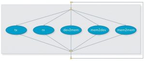
The graph in Figure 6 shows a simple scenario that we might create using the PSS actions for the IPs in our subsystem. Our goal is to exercise the legal behaviors in the system, so our scenario runs one of the following: a transmit operation on the UART, a receive operation on the UART, or one of the DMA transfer operations. We can certainly build up a few more scenarios from the actions we have available, with the benefit that our scenario descriptions are concise and heavily leverage the modeling work already done by the IP teams.
SoC Level
When we get to the SoC level, the subsystem that we have verified will be combined with a processor subsystem (Figure 7). One big change, from a verification perspective, is that our tests will now run as C tests on the embedded processor in the design.
In addition to this big change, there will be some smaller changes; such as the memory map for the full system. The same PSS benefits of flexibility and configurability that we saw at the block and subsystem levels make it easy to customize our PSS content for use in a SoC environment.
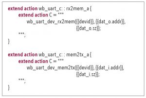
First, let’s deal with connecting our actions to appropriate test realization (implementation) code. The code below specifies a mapping between two of the UART actions and the C code API that implements the behavior described by those actions. Just as we customized our DMA actions for use in a subsystem by extending them with additional constraints, we can extend our UART actions to specify that a C API must be used to implement the behavior instead of SystemVerilog code. These C utility functions and PSS test- realization mapping is part of the IP team’s deliverable, so we really just need to select the right files and compile them.
In many cases, the scenarios that we developed at the subsystem level can be reused with very minimal changes and will provide verification value at the SoC level. This is because at the SoC level, just like at the subsystem level, one of our key verification tasks is to exercise interactions between the integrated IP.
Vertical Reuse axis – benefits and costs
Across this process of PSS reuse from IP to SoC, we have seen several benefits. At the block level, we benefited from the higher-level modeling that PSS enables for creating scenarios. At the subsystem and SoC levels, we reused PSS content created by the IP and subsystem teams, respectively, to be able to create our scenarios more quickly. At the SoC level, we see this particularly in being able to quickly create SoC bring-up tests that leverage scenarios that have already been verified in a UVM-centric verification environment.
This all sounds good, but there are costs and drawbacks. The primary obstacle to realizing this vision of reusable verification is getting an IP’s entire supply chain to produce reusable PSS test intent. It is challenging to convince even internal IP teams to develop PSS primarily for use by the subsystem and SoC teams. It is even more challenging to convince external IP suppliers to provide PSS test intent, and possibly to go back and develop PSS for IP that already exist. In summary, PSS vertical reuse is a high-benefit, high-cost axis of reuse.
Horizontal Reuse Axis
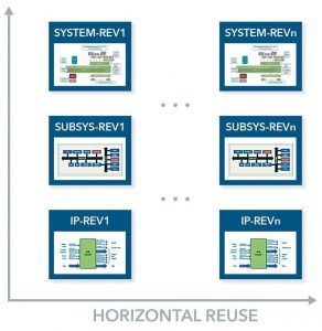
A very large number of design and verification projects are actually derivatives of existing designs. An SoC derivative design might add a hardware IP to accelerate some time-consuming processing. It might, instead, remove some of the dedicated hardware accelerators to create a lower-cost version with fewer capabilities. The bottom line is that the majority of the design remains the same (Figure 8).
Of course, the entire derivative SoC must be verified, not just what is different from the previous revision. When SoC integration is verified with a suite of directed C tests that run on the embedded processor in the design, a large number of tests need to be manually inspected and updated to ensure that they properly exercise the new functionality. When functionality is removed, tests must be changed to not exercise the functionality that no longer exists. When functionality is added, use-case tests that should leverage the new functionality must be updated to do so. All of this work is time-consuming, and essentially results in each SoC having its own test suite – despite the fact that it was derived from the test suite for its predecessor.
By contrast, customizing a PSS model to either add or remove functionality to test is simple. As a declarative specification, new rules (in the form of constraints) can simply be layered on to a PSS model to customize the functionality being tested.
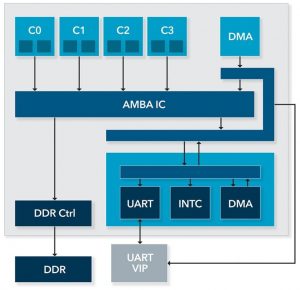
Consider the design in Figure 9. It has two DMA engines — one in the peripheral subsystem and one at the SoC level. What if we create a derivative design that omits the system-level DMA, while leaving the peripheral-subsystem DMA in place? If our verification test suite uses hand-written directed tests, we will need to check each of them (or a substantial set) to ensure it doesn’t attempt to run any activity with the system-level DMA engine.
With PSS, customizing our test suite is much simpler. The following code was used in the original SoC to allow the DMA engine to work with both subsystem and system DMA engines.
This next code snippet is the customized constraint to restrict the PSS model to only work with the peripheral subsystem DMA.
Once the PSS model has been appropriately customized for the new design, a suite of tests that is appropriate for the new design can simply be generated. This saves significant time in auditing and modifying the test suite, as well as debugging failing tests.
Horizontal Reuse axis – costs and benefits
Horizontal reuse is a more-targeted application of portable stimulus, compared to vertical reuse. A PSS model must be created to exercise the key elements of the design being verified, but there is no requirement to have PSS descriptions for all IP that the organization uses to develop SoCs. Of course, the PSS model does need to specify how the design IP are to be exercised, so developing the PSS model to exercise the IP could still represent a significant expense. Since the requirements scope is much smaller than vertical reuse (bounded to a project group), the logistics for implementing horizontal reuse are significantly simpler than the logistics for implementing vertical reuse.
Horizontal reuse delivers fewer overall benefits than vertical reuse, but the benefits in time savings across project revisions are very significant. Moreover, the startup costs are significantly lower compared to vertical reuse.
Technique Reuse axis
Nearly every test environment has a need for high-quality automated stimulus. Whether you are verifying a C++ design for high-level synthesis, a Verilog or VHDL block, or an SoC, it i critical to hit the corner cases and leverage test automation to do so.
A key challenge is that many test environments do not natively offer automated stimulus generation. SystemVerilog provides constrained-random generation and functional coverage as part of the language. Consequently, verification engineers using SystemVerilog and UVM have ready access to automated stimulus generation. Users working in C++ or embedded C do not have a constraint solver to work with and are either restricted to directed tests or to environment-specific solutions for automating test generation. As illustrated by Figure 10, PSS provides a way to describe a model from which tests can be automatically generated that works across languages and environments. This allows users to leverage knowledge of the PSS language and leverage tools that process PSS instead of working with a variety of custom solutions.
Technique Reuse Axis Costs and Benefits
Technique reuse has the smallest startup costs of any of the techniques. The primary cost is determining how the PSS model will connect to existing utility code to exercise the design. As such, it might be necessary to reorganize some existing code to make it easier to call from PSS. This work is really just reorganizing code to make it more modular and is just good software engineering.
In addition to having the smallest startup costs, technique reuse provides the smallest overall benefits, though the benefits can be significant. Unless coupled with horizontal reuse, technique reuse results in tests that are locked to a specific project, though the tests may be reused across different execution platforms.
Focusing on Reuse
The three axis of reuse are guideposts along the path to portable stimulus adoption and proliferation. Understanding the role they play in your design projects provide the coordinates of where to focus your portable stimulus efforts so that your team will succeed on the big stage of systems.
Further reading
Managing and Automating HW/SW Tests from IP to SoC
Jump-Start Portable Stimulus Test Creation with SystemVerilog Reuse
About the author
Matthew Ballance is a Product Engineer and Portable Stimulus Technologist at Mentor, a Siemens Business, working with the Questa inFact Portable Stimulus product. Over the past 20 years, Matthew has worked in product development, marketing, and management roles in the areas of HW/SW co-verification, transaction-level modeling, and IP encapsulation and reuse. He is a graduate of Oregon State University.
