Make it easier to exercise state machines with SystemVerilog
How the use of declarative, constraint-based descriptions can help you focus command sequences on areas of interest.
Exercising state machines is key to verifying design functionality. Indeed, state machines are so important that the Accellera Portable Stimulus Standard (PSS) provides specific features for modeling activities that sequence design machines through their states.
The support that the PSS provides for state machines is adequate for exercising state machines, but we can get many of the same benefits of more-productive modeling and automated test creation in SystemVerilog as well.
In this article, we will show how to model command-sequence generation for a state machine in SystemVerilog, and we will see how this enables more-productive modeling and better test generation.
Exercising a memory state machine
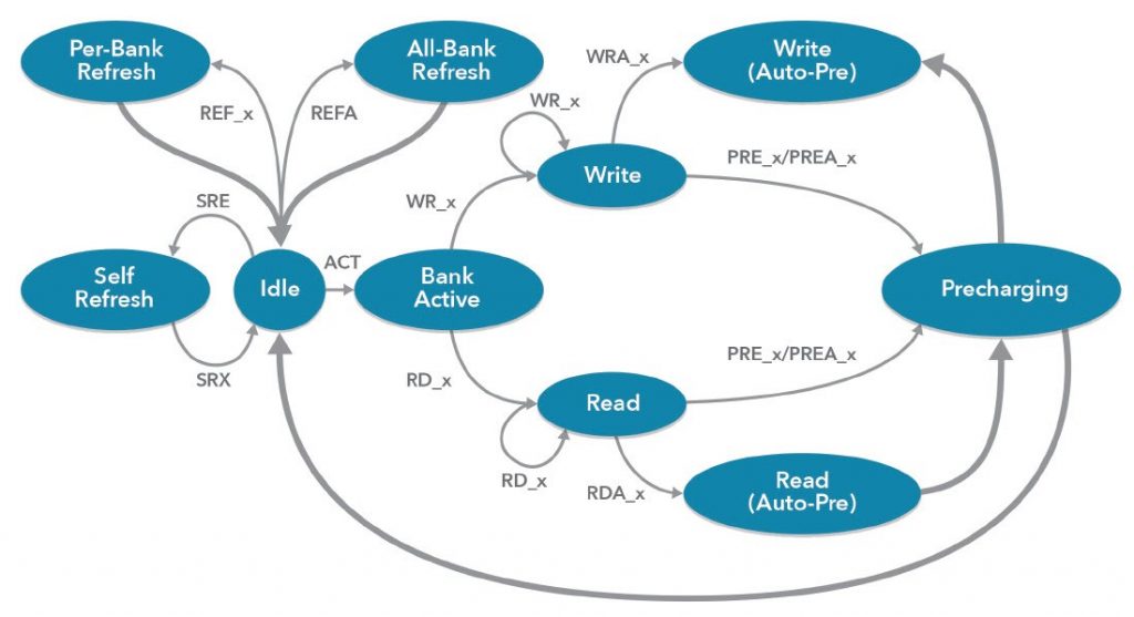
We will use a state machine for an LPDDR SDRAM memory to illustrate our approach. A generic and slightly-simplified LPDDR diagram is shown in Figure 1, along with the relevant states and commands that provoke these transitions.
This state machine may appear deceptively simple; yet exercising all the valid three-deep sequences of commands is far from trivial. Much of the complication comes from the fact that we do no t just need to exercise the state machine. We also need to ensure the design is in a state where transitions in the state machine can be exercised.
In order to write stimulus for generating LPDDR commands to exercise the memory device’s state machine, we will capture the constraints that relate the device state to each of the three commands. Constraints are a declarative description. Capturing the legal command sequences in this way allows us to easily constrain the command-sequence generator to produce specific command sequences, and it allows us to apply automation for generating test sequences and coverage.
The LPDDR state machine, like many others, is conditioned by the device state. For example, in order to perform a write (WR_x) on one of the banks, that bank must be in the active state. Our first task is to identify the device states that dictate the valid commands that can be applied at any given point in time. With LPDDR, there are two elements of state to be aware of:
- Whether the device is in the self-refresh state
- Whether a given bank is active
We start by capturing these state elements in a struct, as shown in Figure 2 (Note that in this LPDDR memory, there are eight banks).
We will use this state to condition the set of commands that can be generated.
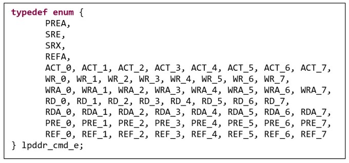
The first thing we need to do in forming the command-generation constraints is to identify the set of commands. The enumerated type shown in Figure 3 encodes every command that can be applied — either globally or to a specific bank.
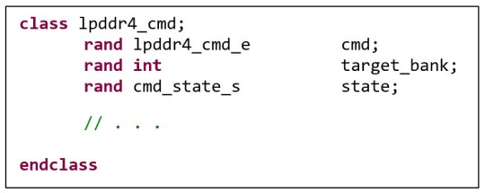
We next capture everything necessary to describe a single command within a class, as shown in Figure 4.
The single-command class captures the following:
- the device state prior to execution of the command (the state field);
- the command to be generated; and
- the target bank (if applicable) to which the command is applied.
Now we need to form constraints that reflect the rules expressed in the state machine as constraints against the current state.
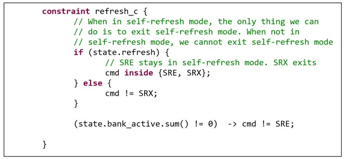
Figure 5 shows the constraints necessary to encode the arcs between the idle state and the self-refresh state. Note that the only thing we can do while in the self-reset state is to stay in that state or exit the self-refresh state. When we are not in the refresh state, we cannot issue a self-refresh-exit command. Finally, we cannot issue a self-refresh command unless all the banks are idle.
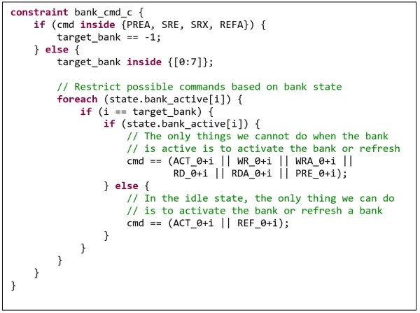
There are a similar set of constraints to control when bank-specific commands can be issued, as shown in Figure 6.
Here the constraints primarily ensure that specific commands can only be issued when the appropriate bank is activated. We can trace these restrictions back to the rules described by the state machine shown in Figure 1.
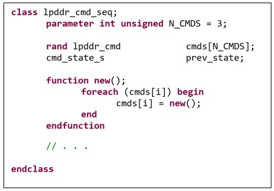
Now we need to capture the rules around sequences of commands. Recall that we are targeting the generation of sequences of three commands. Consequently, we define a three-deep array of the command classes we have already discussed.
Note that we also capture the previous state, which will be the state of the device after the last command of the sequence executes (or the initial state).
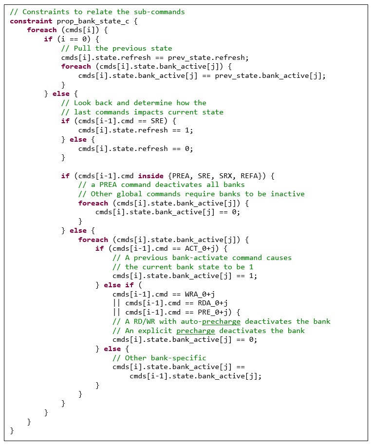
The constraints shown in Figure 8 compute the value of the state variables at each step of the command sequence, based on the command that is executed. For example, if the last command was SRE (self-refresh enter), then the state of the design for this command will be ‘refresh’. Note also that the state of the first command is set to be equal to the state from the end of the previous command sequence, captured in the ‘prev_state’ field. We have now defined the stimulus model for generating three-deep command sequences of LPDDR commands.
Modeling command sequences
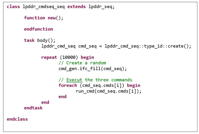
Our command sequence is generated as a unit of three commands. Our testbench likely will want to work with each of those commands individually. The integration approach we take, as shown in Figure 9, is to generate three commands at a time, then apply them one at a time to the testbench via the ‘run_cmd’ task.
Modeling the command sequence declaratively using constraints enables us to easily shape the command sequence by constraining elements within it. Modeling the command sequence in this way also enables us to leverage automation that understands the constraint relationships.
One challenge we will face in generating all legal command sequences is collecting the functional coverage to prove that we did so. A key challenge, here, is that a significant number of the apparently valid sequences are actually invalid due to the constraints across the command sequence. Consequently, creating the functional coverage description by hand is very difficult.
Fortunately, automation tools such as inFact from Mentor, a Siemens business understand the constraint relationships and can automatically generate functional coverage and the exclusion bins to mark cases that the constraints make unreachable.
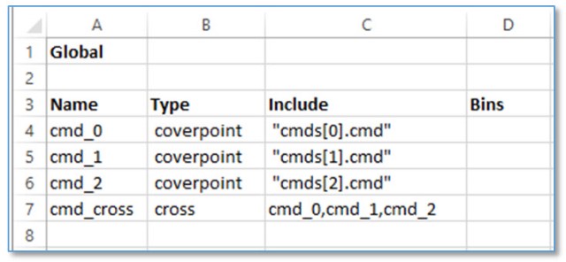
The first step is to capture the coverage goals in a CSV (comma-separated value) file, as shown in Figure 10. The description is very high level, and simply states that a coverpoint must be created on each of the ‘cmd’ fields, and a cross coverage must be created from those coverpoints.
Our coverage specification simply needs to capture the goals we care about: a cross between the three commands in the three-deep command sequence array.
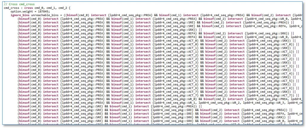
Because our command sequence is captured in constraints, the reachable and unreachable combinations can be identified via static analysis. This enables the exclusion bins (see Figure 11) to be automatically generated, instead of laboriously created by hand. This is a significant savings compared to specifying things declaratively.
Static analysis can also tell us exactly how many combinations are reachable — 187,845 in this case.
Gaining advantage in command-sequence generation
As we have seen, command sequences are a powerful way to exercise a sequential design, and the use of constraints to generate command sequences allows us to automate test creation. Using declarative, constraint-based descriptions makes it is easy to focus command sequences on areas of interest. Because the state space is completely modeled in a statically-analyzable manner, it enables automation tools like inFact to generate SystemVerilog functional coverage. This pattern for modeling the relationship between commands can give you a big advantage next time you face a command-sequence generation challenge.
Further reading
To learn more about how portable stimulus makes it easier to create reusable scenarios, download the whitepaper, Building a Better Virtual Sequence with Portable Stimulus. Find even more Portable Test and Stimulus resources, including courses and Virtual Labs, on Verification Academy.
About the author
Matthew Ballance is a Product Engineer and Portable Stimulus Technologist at Mentor Graphics, working with the Questa inFact Portable Stimulus product. Over 20 years in the EDA industry, he has worked in product development, marketing, and management roles in the areas of HW/SW co-verification, transaction-level modeling, and IP encapsulation and reuse. Matthew is a graduate of Oregon State University.
