EUV’s arrival demands a new resolution enhancement flow
The transition from optical to extreme ultraviolet (EUV) lithography in high-volume manufacturing is underway. Some issues are still being ironed out but the resolution enhancement technology (RET) flow is ready. The computational lithography software has been in development for many years and has already been deployed at a number of leading-edge fabs.
EUV presents some unique challenges that today’s RET and optimal proximity correction (OPC) tools need to resolve. For example, the accurate computation of the density-dependent component of flare and the elimination of the imaging impact from black border effects. Moreover, the entire process—including the scanner, materials, resist, and process integration—is still evolving. This presents new challenges and opportunities to improve the RET flow.
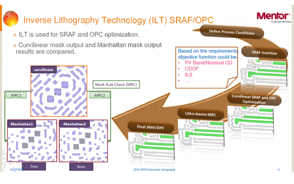
Consider the question of whether sub-resolution assist features (SRAFs) are needed. Do they improve the process margin with EUV? If so, what is the ideal approach? EUV RET optimization for next-generation designs involves co-optimization and many complicated trade-offs. In a joint effort with GLOBALFOUNDRIES and IMEC [1], Mentor found that with powerful optimization tools, such as inverse lithography techniques, and a careful balancing of requirements, SRAFs are very useful. Here are two examples.
Figure 1 shows how SRAFs can provide an enabling element to achieve required process latitudes.

Figure 1. Using inverse lithography for EUV SRAF and OPC optimization (Mentor/GlobalFoundries/IMEC – click for full-page view)
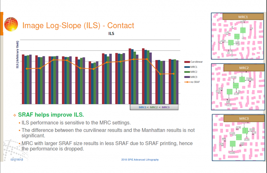
Figure 2 shows how SRAFs can help improve image quality and process window, and mitigate image shift through focus.

Figure 2. Optimized SRAFs can help improve ILS (Mentor/GlobalFoundries/IMEC – click for full-page view)
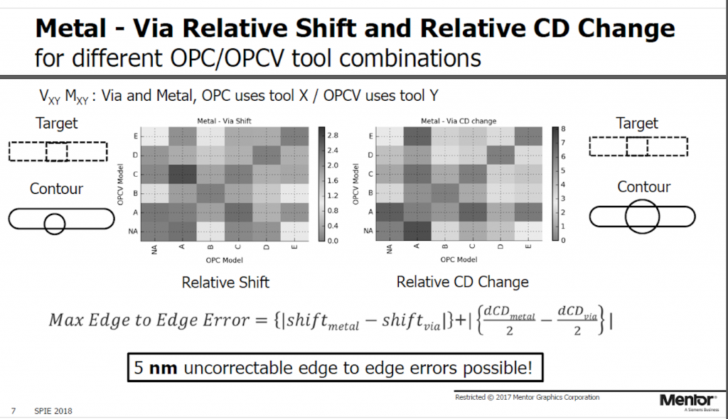
Another challenge is the impact of aberrations on EUV lithography. We can adequately simulate and correct EUV scanner aberrations during OPC across the slit to deliver excellent edge placement control. The problem is that the level of aberration variability from tool to tool is currently significant and leads to uncorrectable edge-placement errors if OPC is done using one tool while exposure happens on a different tool. This means that the current and near-term anticipated aberrations levels on EUV scanners imply very significant edge-control challenges.
There are a substantial number of combinations of aberrations referenced in OPC, and aberrations referenced in verification across two layers with critical inter-layer edge placements for a fleet of EUV scanners in manufacturing. However, certain combinations yield better lithographic results than others. Computational lithography can be a powerful tool for assessing these combinations for manufacturing use. Mentor has demonstrated the clear advantage of using dedicated OPC models with tool-specific aberration correction. Without such models, uncorrectable relative edge placement errors of up to 5nm can be realized (Figure 3).

Figure 3. Up to 5nm of uncorrectable relative edge placement errors (Mentor – click for full-page view)
Building a fast and accurate OPC flow for EUV
High-volume tapeout flows that apply retargeting, SRAF insertion, and OPC typically exploit design hierarchy to minimize total flow time. This strategy has enabled leading-edge foundries to meet time-to-market requirements with the Calibre platform. Proper use of design hierarchy can demonstrably reduce tapeout flow runtime by between two and 10 times, depending on design type. Ideally, an EUV tapeout flow should try to use as much of the design hierarchy as possible to constrain runtime. But long-range flare and mask-shadowing effects complicate the use of design hierarchy in OPC.
Mentor has focused on creating a flow that preserves as much of the design hierarchy as possible without compromising accuracy or the process window. Our SRAF solution can, for example, safely use ‘local’ EUV models. That is, for small variations in flare, the SRAF placement does not need to consider flare across the chip; the variations can be approximated. This allows for the use of design hierarchy for SRAF placement. The OPC flow for EUV is designed to maintain hierarchy with no loss in accuracy when the full, global EUV models are used. Using Calibre’s advanced hierarchical flow instead of a fully flat flow accelerates runtime by 2.3X on average with no loss in accuracy.
EUV roadmap
It looks like the semiconductor industry will follow an ‘EUV-to-the-end-of-the-roadmap’ strategy. Starting at the 5nm node, EUV will likely find its way into high-volume production alongside multi-patterning. This will continue at 3nm. Beyond that, there may be help from the scanner hardware side with a planned increase in the numerical aperture (NA) to >= 0.5 (from today’s 0.33). This will provide an increase in resolution, but at a cost. The industry will probably adopt an optical system with anamorphic magnification – 4x in the x-direction, and 8x in the y-direction. This will require reticle layouts to be split in half along the x-axis, and each half ‘stretched’ along the y-axis and placed onto different reticle plates. Although no such full-field exposure tools exist today, Calibre’s modeling and mask synthesis solutions already support anamorphic optics from modeling through OPC and on to mask data-prep and mask process correction.
EUV lithography is nearly ready to support high-volume manufacturing at 7nm and beyond. Although it has presented many new challenges for OPC and RET in terms of accuracy and runtime, the tools are now ready. Production solutions for modeling and correction for flare, off-axis illumination, and aberration effects exist and have been integrated into a fast advanced hierarchical platform within Calibre.
References
[1] ‘SRAF requirements, relevance, and impact on EUV lithography for next-generation beyond 7nm node’, Guo et al, SPIE Advanced Lithography 2018. This paper is available for download to SPIE subcribers and on a paid basis for others.
 Gandharv Bhatara is the product marketing manager for the Calibre OPC/RET products at Mentor, a Siemens Business.