EDA innovation is the foundation of progress
EDA companies constantly evaluate and experiment with the design information they receive from design houses and foundries. Together with these partners, they often establish collaborative projects to assess the impact of changing technology, and to develop and implement new functionality and tools that reduce or eliminate time and resource impacts while ensuring accuracy and full coverage. Constantly replacing and updating inefficient, less precise, or manual verification processes with smarter, more accurate, faster, and more efficient automated functionality helps maintain, and even grow, the bottom line and product quality in the face of increasing complexity.
However, as the EDA industry, along with design companies and foundries, keeps bending over backwards in the effort to keep Moore’s Law moving forward, it is continually confronted with new challenges. For example, the use of finFETs and the introduction of gate-all-around (GAA) finFETs present questions of performance, scalability, and variation resilience that have yet to be fully resolved. The need for multi-patterning has been in place since the 22nm node and is not going away, even with the introduction of extreme ultraviolet (EUV) lithography. Just the opposite has occurred. More multi-patterning processes have been introduced. Complex fill requirements have emerged as a critical success factor in both manufacturability and performance in leading-edge nodes.
These factors, among others, have had significant impacts across the design-to-tapeout ecosystem, particularly in physical verification. The counts for rules and rule operations continue to increase (Figure 1) and this increases runtimes and memory usage in turn. A collateral effect is the increase in design rule checking (DRC) error counts, resulting in the need for more DRC iterations between the start of physical verification and final tapeout.
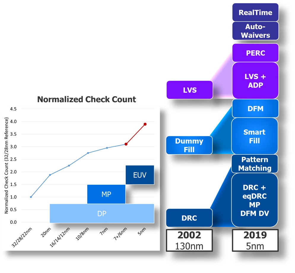
Figure 1. Maintaining design performance and manufacturability at advanced nodes has required a significant growth in design rules and associated checks (Mentor)
The good news is that solutions are coming. In fact, many are available now. This article looks at some of the most influential changes EDA companies are making, using the Calibre platform from Mentor, a Siemens business to illustrate how they are being translated from ideas to practical applications.
Foundry partnerships
For an EDA company, the key to being ready for the next node is to work with the foundries while that node is in development. The identification, analysis, and development of new checking capabilities takes time. Maturing that new functionality into a verification flow with high performance, low memory, and good scaling takes even longer. EDA companies cannot wait until a foundry has a new production node completely in place before starting to develop and implement the new and expanded verification and optimization capabilities that will be needed.
At the same time, they also cannot successfully develop robust new functionality based only on the requirements a foundry identifies in the early stages of node development. Experience shows that foundries, like everyone else, learn as they go during a typical process-development cycle. Not only do the process requirements change, but so do expectations of what the verification tools will be able to do, evolving as the foundry begins uses the tools in the light of new design requirements.
That is why one of the most valuable returns from a foundry partnership is to have the foundry use an EDA company’s tools internally as they develop a new process. That real-time, iterative cycle of developing new functionality and evaluating the results with that set of tools not only helps the foundry fine-tune the design kit requirements, but it also allows the EDA company to simultaneously fine-tune and mature its verification tools, long before design customers begin using them.
A foundry’s ‘golden’ DRC tool is used for the development and verification of test-chip intellectual property (IP) through early versions of the sign-off deck. In that process, the DRC tool is used to help define and validate the new process design rules, validate all IP developed by the foundry in that node, and help develop and validate the regression test suite with which other DRC tools will be validated. All this work, and the thousands of DRC runs on thousands of checks and tens of thousands of checking operations, not only hones the accuracy of the foundry’s primary DRC tool, but also helps set the standard for other DRC tools. This typically happens months to years before other DRC tools can even begin their validation. That is why certification is only a minor part of what it means for an EDA company to partner with the foundries.
One measurable example of this advantage can be seen by tracking the performance of DRC decks across the pre-production release cycle. Physical verification tools are, at their core, a specialized programming language for writing design rule checks. Just like in any programming language, there are both efficient and inefficient ways to write the code. Mastering the art of writing good checks takes a lot of skill and time. Working directly with both the foundry teams that generate the design rule decks and the internal teams that use them as they are being written enables an EDA company to identify and suggest opportunities for coding optimizations, all throughout the development process. This interactive feedback means that by the time the process goes into production, the decks run significantly faster as a result of those optimizations.
Figure 2 shows how much deck optimization can affect runtime. For example, Version 1.0 (the first full production version) of a Calibre deck runs nearly 70% faster than version 0.1 written very early in the process development cycle. This improvement has nothing to do with the verification tool itself; it is completely the result of implementing best coding practices.
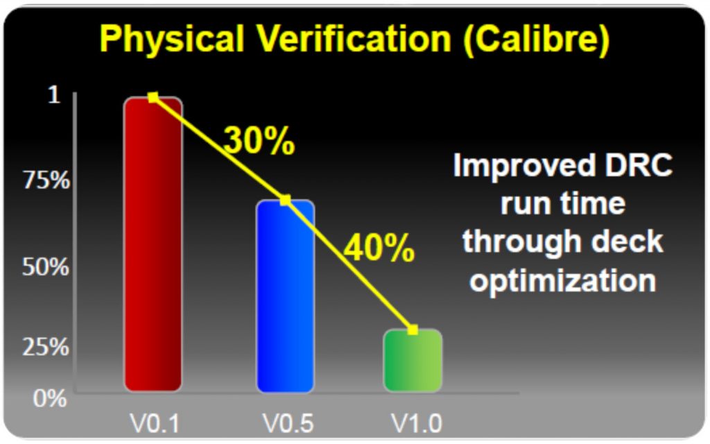
Figure 2. Reduction in DRC normalized runtimes achieved by rule deck optimization by foundry release version (Mentor)
For mutual customers, the benefit extends beyond this collaborative learning. Design houses using the same verification software their foundry uses during the development process can learn about and implement these new design requirements, as well as about tool functionality changes and optimization, while the process node is still in development. That means their designs are typically going to be production-ready in conjunction with, or shortly after, that process node becomes commercially available, enabling the fastest possible time to market.
Runtime optimization
Engine improvements
Frontline components for combating the explosive compute challenge include raw engine speed and memory. For instance, although the Calibre toolsuite has been around for decades in name, Mentor constantly optimizes the underlying code base, even completely rewriting portions. It does this not only to add new functionality, but also to continuously improve performance, and, today, to take advantage of evolving distributed and cloud-computing infrastructures.
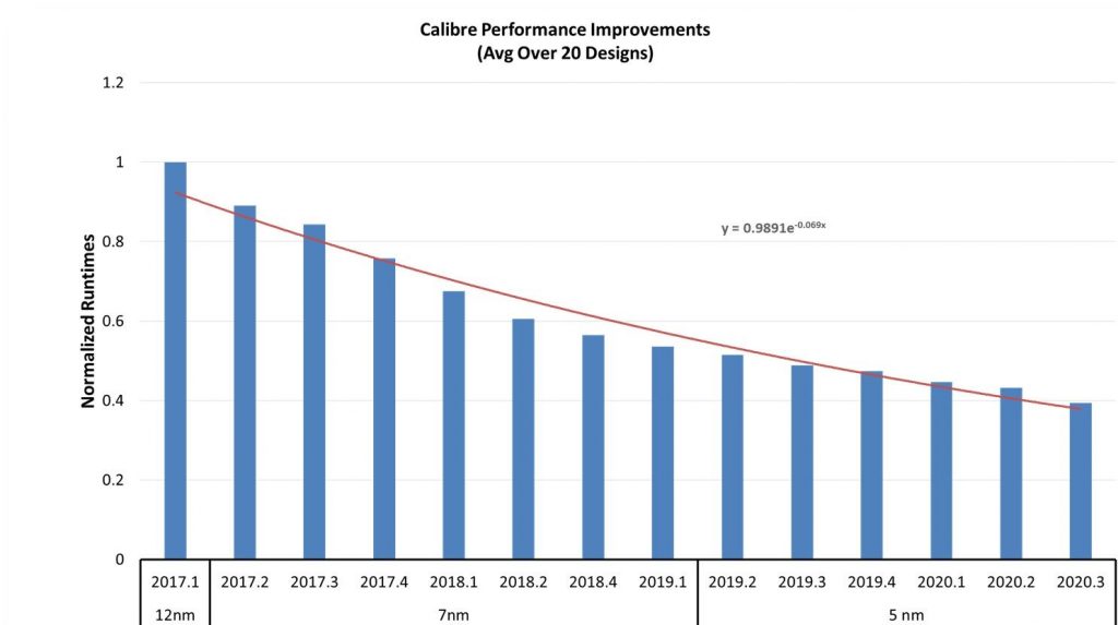
Figure 3 shows a trend of normalized runtimes for the same Calibre nmDRC runset by software version release. Each data point is an average of 20 real-world customer designs, demonstrating (by holding everything else constant) the isolated improvement of the underlying Calibre engine over multiple software releases. Over this three-year time span, engine speed increased by 60%. This trend is indicative of the way Mentor optimizes performance for all of the Calibre physical and circuit verification tools [1].
Engine scaling
In addition to improving the base engine performance, EDA companies must also address the explosive growth in computational requirements by effectively utilizing modern compute environments and distributed CPU resources to increase overall compute power. For example, to support this massive increase in compute time, the Calibre architecture employs a hyperscaling remote distributed processing capability that supports scaling to thousands of remote CPUs/cores (Figure 4).
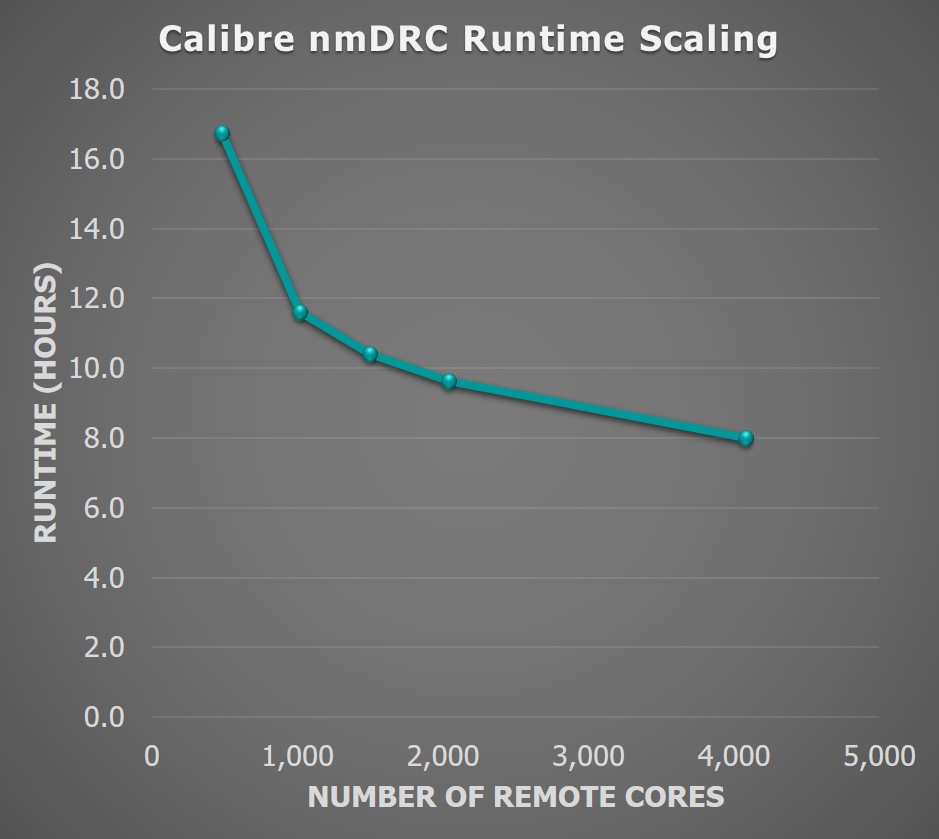
Figure 4. Engine scaling by CPU count. This graph represents a full-chip DRC run for a production customer 16nm design and foundry rule deck (Mentor)
Cloud computing
With 2x more transistors being added node over node, and ever-larger and more complex foundry rule decks, the amount of computing required for today’s designs makes it challenging to obtain and support the processing and memory resources needed to maintain fast design rule checking (DRC) runtimes on premise. Increasing the number of CPUs on-site is not a simple task—hardware acquisition, grid installation, and maintenance all consume time and money. More importantly, even when overall capacity might be available nominally, on-site grids often lack or constrain immediate additional resource availability, forcing time-consuming waits for sufficient resources.
Cloud computing provides an opportunity to accelerate the time to market for designs, particularly when you consider the growth in computing at advanced nodes. By removing cost and latency barriers to resource usage, cloud computing allows companies to leverage the scaling capability of EDA software by obtaining instant access to the CPU resources needed to achieve their physical verification turnaround time goals (e.g., overnight runtimes), even in the face of the exponential compute growth at the latest nodes. Having access to EDA technology in the cloud can also provide a fast, cost-effective means of dealing with situations that arise when all internal resources have already been committed.
Another barrier preventing the adoption of EDA in the cloud has been the lack of sufficiently strong protection for proprietary intellectual property (IP). With improvements in cloud security eliminating the industry’s concern over IP protection, this obstacle has now been removed [2].
Of course, as with any new operating model, companies are looking for support in the form of usage guidelines and best practices. As the use of EDA in the cloud has expanded, a few operational efficiencies have been identified.
Use the most recent foundry-qualified rule deck. Doing so ensures that the most recent coding best practices are adopted, assuring users of optimized runtimes and memory consumption, as shown in Figure 5.
- Figure 5. Calibre memory and performance improvements in subsequent Calibre release versions (Mentor – click to enlarge)
Implement a hierarchical filing methodology, in which a design is sorted into cells that are later referred to in the top levels of the design. This technique significantly reduces data size and enables a significant reduction in final sign-off runtimes.
Take advantage of any EDA software modes that support faster and/or more efficient use of distributed resources. For example, the Calibre HDBflex process allows users to connect to the primary hardware only during the hierarchical database construction. This sequence eliminates idle resource time by ensuring that the majority of the database construction takes place in the multi-threading (MT) only mode, connecting to remotes only in the later stages of construction. Using the Calibre HDBflex construction mode substantially reduces the real time that the remotes are idle during the creation of the hierarchical database (Figure 6).
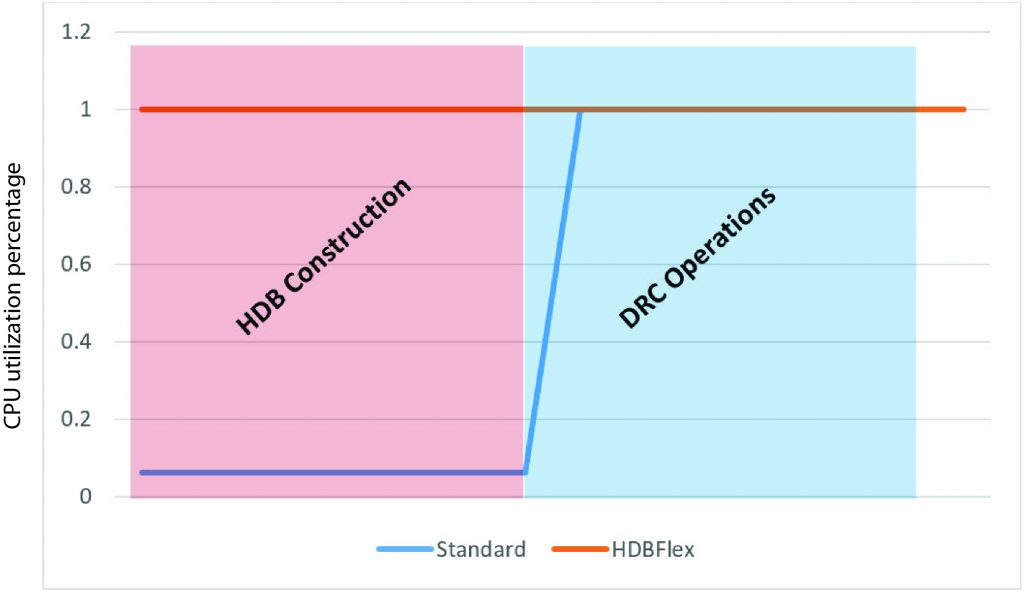
Figure 6. Software modes that optimize CPU utilization in a distributed processing environment like the cloud improve speed and efficiency (Mentor)
Choose geographically close cloud servers to reduce network latency time. Cache-based systems will also improve machine performance. To minimize upload time, upload each block separately as it is available, along with standard cells and IPs, then upload the routing. By uploading in stages, users avoid any bottlenecks. They can then use their EDA software’s interface in the cloud to assemble all the data. Figure 7 shows the standard cloud setup for the Calibre platform.
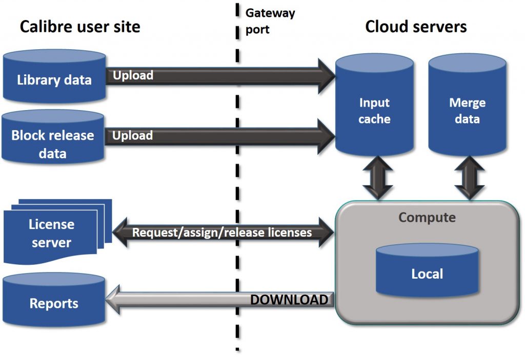
Figure 7. Uploading blocks and routing separately, and combining the data in the cloud server minimizes upload time and potential bottlenecks (Mentor)
Innovative functionality
Every EDA software supplier constantly works to provide new and expanded functionality to enable users to complete their IC designs, verification optimization, and tapeout more quickly, more accurately, and more efficiently. To illustrate this, we can look at a few of the ways Mentor has added functionality to the Calibre platform to address specific issues that might affect a design company’s ability to maintain tapeout schedules in a highly competitive market.
Earlier verification
Given the size and complexity of advanced node designs, combined with the never-ending competition to be the first to market, system on chip (SoC) design teams do not have the luxury of waiting until all chip blocks are completely finished to start their chip assembly. Accordingly, SoC designers typically start chip integration in parallel with block development to capture and correct any high-impact violations early in the design cycle, helping them reduce that critical time to market. By eliminating errors early, when they are easier to fix without significant impacts on the layout, designers can reduce the number of sign-off iterations required to achieve tapeout (Figure 8).
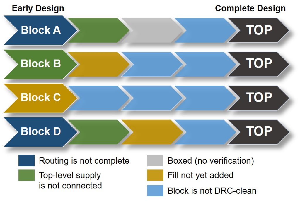
Figure 8. Identifying and fixing chip integration issues in parallel with block development minimizes the number of signoff iterations throughout the design implementation flow (Mentor)
At this early stage, the designer’s goal is usually to focus only on the violations that are relevant at this time, while minimizing verification runtimes. However, early chip-level verification faces many challenges. Typically, during very early phases of floorplanning, the number of reported violations in the unfinished blocks is huge. Many systemic issues may be widely distributed across the design, contributing to this large error count. Characteristic examples of systemic issues include off-grid block placement at the SoC level, merged IP outside the SoC MACRO footprint, routing in IP on a reserved routing layer, shorted nets, soft connection conflicts, etc. It is no trivial task at this stage to differentiate between block-level violations and top-level routing violations.
The Calibre early verification suite is a growing package of functionalities that enable design teams to begin exploration and verification of full chip design layouts very early in the design cycle, while the different components are still immature. Using various techniques to optimize early verification, the Calibre early verification technologies are very effective in identifying potential integration issues and providing fast feedback to design teams for proper corrective actions.
For broader applicability, Calibre early verification technologies are engineered to work with foundry/independent device manufacturer (IDM) Calibre sign-off design kits without modification and on any process technology node.
Calibre nmDRC-Recon design rule checking
Not every design rule check is needed at every phase of design verification. Running only the necessary and applicable rules can save significant time in the overall tapeout schedule. The Calibre nmDRC-Recon technology automatically deselects the checks that are not relevant for the current development phase [3]. The Calibre nmDRC-Recon engine makes the decision on which checks to deselect, based on the check type and the number of operations executed for the check, with the goal of providing good coverage, fast runtime, and less memory consumption.
On average, the Calibre nmDRC-Recon technology reduces the number of checks performed by about 50% across a range of process nodes. Automatic deselection of checks typically results in a 30% reduction in the total number of reported violations, compared to a full DRC run (Figure 9). However, these violations are more meaningful to the targeted implementation stage, which facilitates analysis and debugging of real systemic issues.
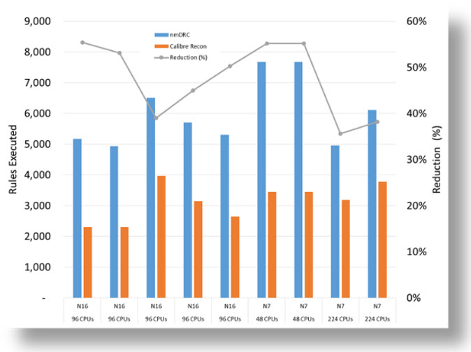
Figure 9. Reductions in the total number of rule checks performed and the resulting number of reported violations when using Calibre nmDRC-Recon functionality (Mentor)
The Calibre nmDRC-Recon technology typically reduces overall DRC runtime by up to 14x, while still checking approximately 50% of the total DRC set. The subset of rules used are effective in identifying significant floorplan and sub-chip integration issues, providing fast feedback to the design team for proper corrective action.
Calibre nmLVS-Recon circuit verification
The Calibre nmLVS-Recon tool introduces a more intuitive approach to early-stage circuit verification to enable designers to execute only those checks required to solve the highest-priority circuit issues [4]. Design teams can easily toggle between different configurations, and decide which issue(s) they want to focus on in every round of execution.
One of the unique aspects of circuit verification is the heavy connectivity dependency and the complex hierarchical context required to establish the base for fully-executed LVS verification. To implement targeted verification, the Calibre nmLVS-Recon intelligent heuristics assist designers in determining which circuit verification requirements must be performed for maximum efficiency, and executing only the selective connectivity extraction required to complete the targeted analysis.
The first use model available in the Calibre nmLVS-Recon tool focuses on short isolation and short paths debugging, executing only those steps of connectivity extraction that are needed to construct the required paths for short isolation analysis. Built-in options enable engineers to further delineate those areas in the design that are of particular interest:
- Layer-aware short isolation divides the design into layer groups to analyze shorts on specific layers of interest
- Net-aware short isolation focuses on critical shorts by targeting a design’s most impactful nets first, as determined by the size of the net and how it propagates throughout the chip.
- Custom short isolation enables customizable input for even more precise short paths analysis and concise per-net iterations
Running shorter targeted circuit verification enables more iterations to be completed, which enables design teams to reduce their overall time to tapeout (Figure 10).
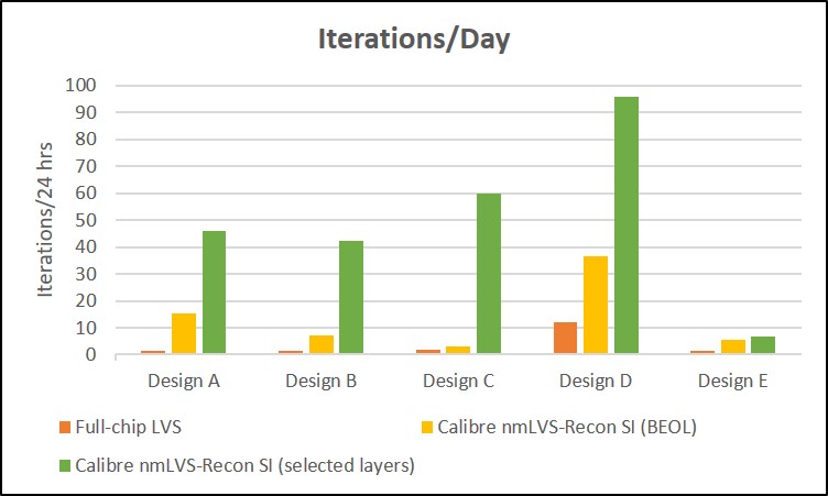
Figure 10. Using the Calibre nmLVS-Recon short isolation verification for back-end-of-line and selected layers enables designers to increase iterations significantly over full LVS verification (Mentor)
All of the Calibre early design tools are seamlessly integrated with the Calibre RVE™ results viewer for results review, error visualization, and on-the-fly error fixing and verification, prior to fix consolidation. This integration helps designers more quickly analyze their designs and visually examine the distribution of errors to identify the opportunistic areas for quick enhancement of layout quality. Designers can draw different histograms (based on hierarchical cells or windows) for chip analysis, and specify custom scaling ranges for these histograms. Colormaps of the results can also be drawn, either on standalone windows or mapped on the design, to enable designers to probe down to see error details (per cell and per window), where the results are shown distributed across the design (Figure 11).
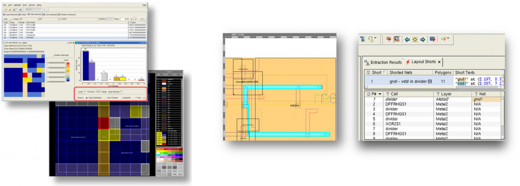
Figure 11. Fast, in-depth layout visualization and analysis speeds error review and debugging (Mentor)
Taking advantage of innovative early design verification functionality enables more early-stage verification iterations, which ultimately significantly reduces total turnaround time, and results in faster time to market.
Conclusion
Integrated circuit design and verification only gets harder and more time-consuming with each new process node. Every foundry expends extensive time and resources to ensure the requirements of that are node are well-understood and accurately defined. Every design company constantly evaluates their design flow and verification tool suite to identify opportunities for faster design development, implementation, and verification. Every EDA company continuously updates, expands, and improves their software platform to incorporate changes in design and verification processes and flows. Time-to-market is a critical commodity in the electronics industry, as is the cost-effective use of resources and engineer expertise. Continuously replacing and updating verification processes with smarter, more accurate, faster, and more efficient functionality that can take full advantage of new technologies and computing environments can improve both the bottom line and product quality.
For more information on our new Calibre nmLVS-Recon tool, watch this short video.
References
[1] Abercrombie, D. and White, M., “IC design: Preparing for the next node,” Mentor, a Siemens Business, March 2019.
[2] El-Sewefy, O., “Calibre in the cloud: Unlocking massive scaling and cost efficiencies,” Mentor, a Siemens Business, July 2019.
[3] Hossam, N. and Ferguson, J., “Accelerate early design exploration & verification for faster time to market,” Mentor, a Siemens Business, July 2019.
[4] Hend Wagieh, “Accelerate time to market with Calibre nmLVS-Recon technology: a new paradigm for circuit verification,” Mentor, a Siemens Business, July 2020.
 John Ferguson is the product management director for Calibre DRC applications at Mentor, a Siemens BusinessHe holds a B.Sc. degree in Physics from McGill University, an M.Sc. in Applied Physics from the University of Massachusetts, and a Ph.D. in Electrical Engineering from the Oregon Graduate Institute of Science and Technology.