Create more flexible virtual sequences with Portable Stimulus
Virtual sequences are considered challenging to write and re-use. Learn how to overcome those issues with the new Portable Stimulus Standard in this DMA-based case study.
Everyone who has used UVM has used sequences to generate stimulus. Simple sequences drive single interfaces using transactions. Virtual sequences control more complex behavior, such as driving multiple interfaces or running a series of lower-level sequences to implement a higher-level test.
While simple sequences are fairly simple to write, virtual sequences are challenging to write. They are even more challenging to design in such a way that they are flexible enough to be reused.
The Accellera Portable Test and Stimulus Standard (PSS) is designed with flexibility and reuse in mind. It can be used in environments ranging from simple block-level environments all the way to complex SoC verification environments. This article shows how the flexibility that PSS brings to creating tests can be applied to creating flexible and reusable virtual sequences.
Crafting a Portable Stimulus virtual sequence
Let’s take a look at how to model a virtual sequence with Portable Stimulus for a DMA engine.
The DMA engine used here is a relatively simple eight-channel DMA engine. It has a register interface for programming DMA transfers, and two master interfaces for the DMA engine to use for transferring data. Each DMA channel can either perform direct memory-to-memory transfers, or can use peripheral handshake signals to transfer data from memory to a peripheral device, or from a peripheral device to memory.
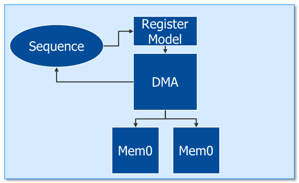
Figure 1. DMA engine testbench (Mentor)
Portable stimulus encapsulates behavior in actions. Our first task is to take a step back and consider which actions we need to create. Our DMA engine can perform three logical functions:
- Transferring data between two regions of memory
- Transferring data from memory to a peripheral device
- Transferring data from a peripheral device to memory
We will represent each of these operations as a PSS action that we can then use in a scenario.
The PSS language allows actions to declare input and output ports, which allow the action to specify what data must be present when it executes, and what data it provides for the use of other actions. One of the first things we need to consider when modeling behavior as PSS actions is what inputs the behavior requires and what outputs it provides.
The memory-to-memory action reads data from a source location in memory and writes it to a destination location. This indicates that we should have an input to represent the source location and an output to represent the destination location. The mem2dev and dev2mem actions will, respectively, read from a region of memory and write to a region of memory. This indicates that they should, respectively, have an input and an output. But, how should we represent the device that these actions interact with? We could represent the device address using an input and output as well, but in this case we will not because we know that the device address is closely linked with the DMA channel used by the mem2dev and dev2mem actions. The device address will be a function of the system address map and the DMA channel in use, not something the test-scenario writer will manipulate directly.
Figure 2 shows our DMA action primitives.
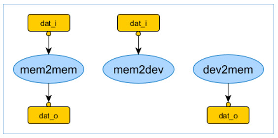
Figure 2. DMA primitive actions (Mentor)
Figure 3 shows the PSS description of our memory-to-memory action. The device-to-memory and memory-to-device actions look very similar, and will not be shown.
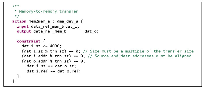
Figure 3. Memory-to-memory transfer action (Mentor)
In addition to declaring the inputs and outputs of the action, we must specify the constraints that govern its operation. Specifically, we must specify that the size of data transferred must be 4k or less – a constraint imposed by the DMA engine. The address of both the source and destination address must be aligned to the DMA’s transfer size as well. Note that the action declaration does not specify anything about how the DMA will be programmed. The action only contains the high-level rules on a DMA transfer. We will add in the mapping to our UVM environment later.
Now that we have low-level actions that represent the core operations the DMA engine can perform, we can assemble those actions into a compound action that carries out a scenario. The scenario we started with was running two DMA transfers in parallel on different channels. An equivalent scenario is shown in Figure 4.
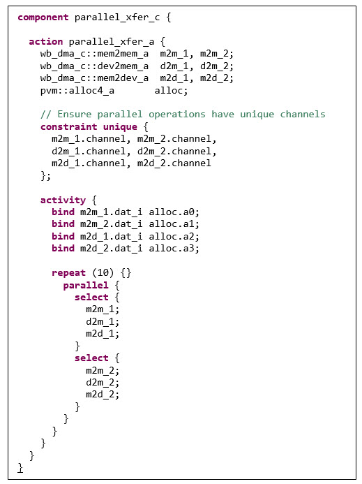
Figure 4. PSS parallel-transfer scenario (Mentor)
The first portion of the description creates instances of our low-level actions for performing DMA transfers. After creating action instances, we create a constraint to ensure that the channel selected for the DMA operations that eventually run will be different. Next, the activity block composes a scenario from the action instances. The parallel construct in PSS makes it just as easy to describe parallel behavior as in SystemVerilog, and the declarative nature of a PSS description enables us to write constraints that apply across the procedure of our test scenario.
Our PSS test scenario weighs in at 40 lines of code, certainly on-par with the roughly 50 lines required for our SystemVerilog sequence, showing that PSS provides a succinct way to capture scenarios.
One challenge with directed-random sequences is that it is difficult to tell whether we have generated the stimulus combinations we really care about. Portable stimulus provides a covergroup construct, just as SystemVerilog does. We can add a covergroup to our portable stimulus model to ensure, for example, that we generate all possible scenarios across our parallel scenarios in our virtual sequence (Figure 5).
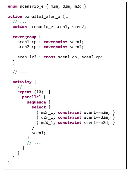
Figure 5. Adding coverage (Mentor)
PSS currently supports data-centric coverage, so we still need to represent the scenarios we need to cover as a data relationship. However, here again, the declarative nature of PSS makes it much simpler to capture the coverage relationships we care about. We add in two enumerated-type variables (scen1 and scen2) to represent the scenario being executed, and add constraints to the activity to force these variables to the appropriate value given the scenario being executed. This adds a few lines to our scenario, but will allow us to ensure that we exercise all the scenarios.
Thus far, we have focused on test intent – the high-level view of what we want to test. In order to actually run traffic in our testbench environment, we need to run sequences or call APIs in SystemVerilog. PSS provides the exec construct to connect the high-level test intent described in PSS to the low-level test realization described in SystemVerilog, C, or any number of other implementation languages.
The exec block shown in Figure 6 provides a mapping between the fields of the mem2mem_a action and a task in our SystemVerilog virtual sequence named wb_dma_dev_mem2mem. This task is responsible for programming the DMA engine to carry out a transfer on the selected channel.
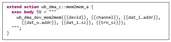
Figure 6. Connecting the Portable Stimulus to SystemVerilog (Mentor)
Customizing our Virtual Sequence
Now, let’s look at the original challenge we faced with our hand-coded virtual sequence: disabling the use of one of the channels. PSS provides us several ways to customize a scenario. The simplest might be to just create a new top-level scenario that inherits from our existing action, and add constraints to force the base action to not use a specific channel (Figure 7). This allows us to reuse our existing scenario, while customizing its behavior.
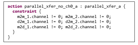
Figure 7. Customizing the scenario with inheritance (Mentor)
The approach we just showed for customizing the scenario targets a specific instance of the scenario. What if we needed to ensure that all instances of the dev2mem action, wherever they appeared in the scenario, never used channel 5? PSS provides a type-extension mechanism that allows us to layer in constraints that will apply to all instances of a given type, as shown in Figure 8.
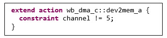
Figure 8. Customizing the scenario with extension (Mentor)
The advantage (and the disadvantage) of this approach is that the new constraint will apply to all instances of the specified type. In some cases, this is exactly what we want. In other cases, we want to be more targeted. PSS also provides a factory-like mechanism that allows us to override types in very specific contexts.
The atomic actions that we created, such as mem2mem and dev2mem, are necessary to support our block-level scenarios. However, there’s nothing tethering them to our block-level UVM environment except the UVM-specific implementation. PSS makes that simple enough to change with another exec block that maps our test intent to a test realization implemented in C (Figure 9).
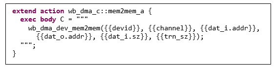
Figure 9. Mapping to test realization in C (Mentor)
The declarative nature of PSS, coupled with appropriate language-specific mapping, makes it very easy to reuse test intent from block level when creating SoC-level scenarios. It doesn’t make sense to reuse all the PSS content we create at block level, since many of the scenarios will test functionality that is specific to block level. However, there are certainly opportunities for reuse at SoC level – infinitely more than with pure SystemVerilog UVM sequences.
Conclusion
Virtual sequences are key to creating complex stimulus in UVM but are often difficult to reuse across projects. Portable stimulus is often viewed as primarily applying to SoC-level testing. But portable stimulus can provide a significant productivity boost by making UVM virtual sequences more powerful, flexible, and reusable.
About the author
Matthew Balance is a verification technologist at Mentor, a Siemens business.
