An easier way to make reliability rules and checks more consistent
Product reliability is a critical component of market success for ICs, especially in fields such as automotive and aeronautic electronics, medical devices, and security systems. Reliability rules define and evaluate various IC design reliability conditions, including electrostatic discharge (ESD) vulnerability, multi-power-domain crossing checks, voltage-aware design rule checking (DRC), and latch-up exposure, as well as company-defined best practices for design reliability.
However, reliability exposure often depends on a complex mix of design conditions. Writing reliability rules and rule checks can be time-consuming, and typically requires the writers to develop expertise in complicated rule syntax. Partly because of these limitations, existing rule files are often copied and modified for use across other designs and technology nodes. Both types of re-use often lead to inconsistencies in reliability rule application.
A new option is making reliability rule development and maintenance faster, easier, and more uniform, for companies that use the Calibre PERC reliability platform for reliability verification. While rule deck developers must still be familiar with the rule syntax to create the actual rules, they can now use extensible markup language (XML) to define each rule’s constraints and associated parameters in a single XML constraint file [1]. The XML language is an open-source language that is widely used, particularly for data representation. It has the advantage of being both human-readable and machine-readable.
A reliability rule XML constraint file contains three sections:
- Includes: This section enables users to include other XML constraint definitions without having to rewrite or copy them. For example, chip designers can include XML constraint files written by intellectual property (IP) suppliers for each IP block that will be placed in the chip design.
- Constraints: This section is where the constraints and their associated parameters and values are defined.
- Aliases: This section is where users can define any existing aliases and their values to simplify and standardize the writing of constraint parameters.
Once an XML constraint file is created, it is passed to the rule-deck users (typically designers) to define the necessary values for the parameters used in their reliability checks, as required by a specific design or technology. Depending on the guidance provided by the rule developer, they may also be able to add or remove parameters. However, the designers do not have to know anything about Calibre PERC rule syntax to define these parameters in the XML file. This makes it much easier for design companies to create and maintain their unique reliability checks.
The XML constraint file can be used with all Calibre PERC topological/voltage and geometrical checks. Because the XML constraint file can be accessed by any Calibre PERC rule file to apply the parameters relevant to that particular rule set, designers no longer need to copy and modify existing rules. The use of an XML constraint file also eliminates any need to write and maintain a parser to read parameters from an external file with a user-defined syntax.
Including other XML files with defined constraint parameters enables the Calibre PERC platform to treat these XML files as if they are local to the primary XML file, ensuring parameter consistency and eliminating the need to create multiple XML files with duplicate information. Commands in the rule file retrieve the necessary XML constraint parameters required by the checks from all the included XML constraint files. The ability to include multiple XML constraint files makes it easy for designers to reference external XML files created for different IP at the chip level.
XML reliability checks
The following code samples demonstrate how the XML code is created. The text is color-coded to identify the different edit capabilities:
- RED text is the XML syntax language for the constraint file. It is created by the rule developer and cannot be edited.
- BLUE text is typically defined by the rule developer, but may be editable by the rule user, depending on the intent of the check. The rule developer can add comments to help rule users understand what fields they are allowed to edit.
- BOLD text is the value a rule user enters for the defined constraint. These values may be dependent on either the design or technology code. For example, a constraint named ‘voltages’ may be design-dependent because it defines design nets and their corresponding voltage values, while a constraint named ‘layers’ is technology-dependent because it defines certain technology layers needed for the
Note: these check examples represent one possible way to code each check. Rule developers and rule users may use different terminology based on their company’s needs and requirements.
Electrostatic discharge
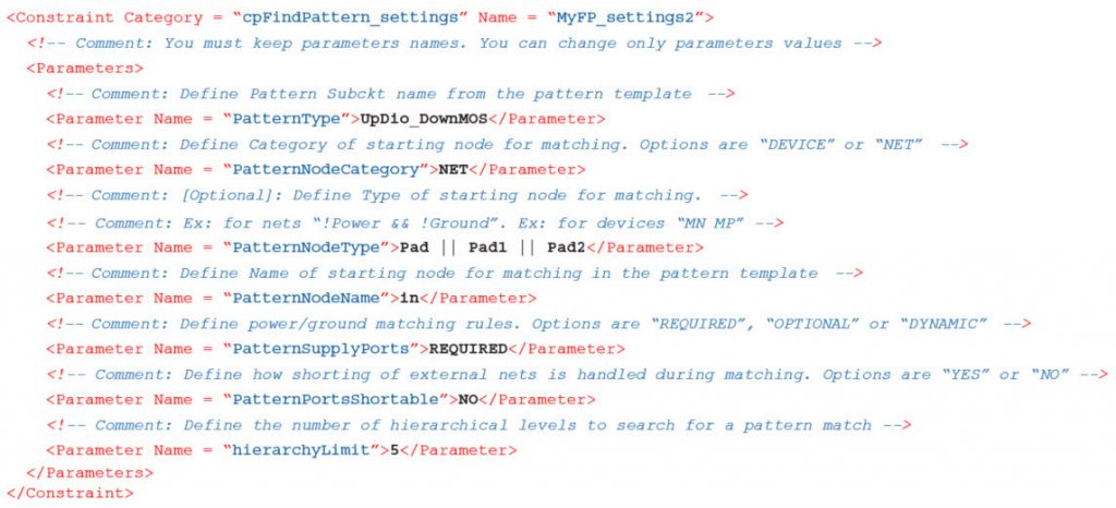
The Calibre PERC ESD rule check depends on using Calibre PERC circuit recognition functionality to capture user-defined circuit SPICE patterns for ESD protection schemes. To support this check, the XML constraints provide parameters to define the values for the different arguments used in the matching process. In this example, the rule developer has defined a constraint category called ‘cpFindPattern_settings’. Comments are used to explain the meaning and any required options for each parameter.
Electrical overstress
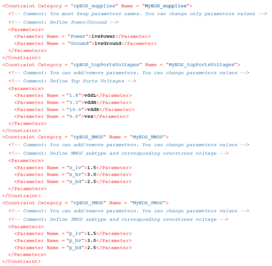
In this electrical overstress (EOS) check, the rule developer has defined four constraint categories:
- ‘cpEOS_supplies’ defines the net names (‘Power’ and ‘Ground’) in the design
- ‘cpEOS_topPortsVoltages’ defines top ports nets with their corresponding voltages
- ‘cpEOS_NMOS’ defines NMOS subtypes and corresponding overstress voltages
- ‘cpEOS_ PMOS’ defines PMOS subtypes and corresponding overstress voltages
The rule developer has also indicated through the comments that the rule user can add or remove parameters for three of these constraints. The rule user entered the appropriate values for each constraint parameter.
Level-shifter
In this level-shifter check, the rule developer has defined a constraint category called ‘cpLevelShifters_settings’ that defines the NMOS subtypes, the PMOS subtypes, and the names for the level-shifter circuit patterns. In this check, the rule user can only change parameter values.
Topology-aware latch-up
The goal of a topology-aware latch-up check is to validate two conditions:
- P+ diffusion connected (directly/indirectly) to an IO pad must be surrounded by a N+ guard ring
- N+ diffusion connected (directly/indirectly) to an IO pad must be surrounded by a P+ guard ring
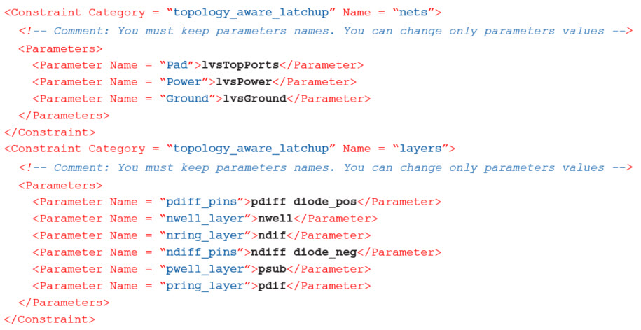
To help designers write checks for this rule, the rule developer must define some parameters to generalize the check. Using XML constraints to create these definitions enables them to quickly create rules that are consistent and accurate. In this example, parameters are defined to capture the pad, power and ground net names, and to capture the different geometrical layers required for this check.
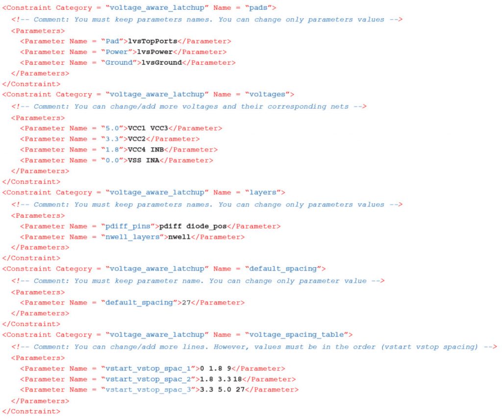
Voltage-aware latch-up
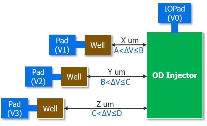
In this voltage-aware latch-up rule, the P+ OD injector separation to Nwell depends on the voltage difference between them (Figure 5). Missing voltage information leads to worst case separation conditions. As with the topology-aware latch-up check, the rule developer must define some parameters to generalize the check. Rule users have the option of changing or adding to the voltage spacing table parameters, providing they follow the required syntax.
Conclusion
Using XML constraint files to define reliability rule constraints, parameters, and values simplifies and standardizes the process for both the rule developer and the rule user, providing greater consistency and accuracy in reliability rule check implementation. The rule developer can create reliability rules using the parameter names defined for the different constraints. Designers can configure checks by defining the necessary values for these parameters within the XML constraint file, without having to access the rule deck or have knowledge of rule syntax. They can also include XML constraint files provided for IP used in the chip. A single XML file can be used by any Calibre PERC rule file, eliminating unnecessary duplication across designs and technology nodes. More reliable reliability rules? Sounds like a good thing.
Learn more about Calibre PERC here.
 Dina Medhat is a senior technologist for Calibre Design Solutions at Mentor, a Siemens Business. Dina received her BS and MS degrees from and is currently engaged in PhD research at Ain Shames University in Cairo, Egypt.