Reliability verification simplified for multi-power domain designs
Reliability verification assesses issues like electrostatic discharge (ESD) [1,2,3], latch up [1], analog layout [4], and other reliability aspects of a layout, It is essential to successful IC design. However, designs that contain multiple power domains present unique design and verification challenges for reliability.
With technological advances and increasing design complexity, an IC often requires more than one power domain. Multiple power domains allow digital blocks to have power domains separate from those used by analog blocks. Multiple power domains are also used to optimize the performance of each block, based on its functionality. Understanding how to detect potential design issues in multiple power domain layouts is critical to ensuring accurate, complete reliability verification for these designs. For example, signal communication between different power domains is required, but proper design techniques and signal protection must be considered to ensure performance reliability. Electrical overstress (EOS) can impact transistor performance if the voltage difference between its gate and its source/drain pins exceeds specified thresholds. To manage this risk exposure, specialized circuits such as level shifters are typically used to control the voltage values between the different power domains.
Multiple power domain design reliability verification
Validating multiple power domain designs requires running multiple reliability checks. These include detection of level-shifters, checking EOS conditions, and detection of cross-power-domain scenarios.
Level-shifter detection
In a multiple power domain design, signal nets must cross from one power domain to another. Because voltages can vary between domains, these crossing nets can often be a point of failure or damage. To control the voltage transition at these crossing-domains interfaces, designers must insert a level-shifter circuit to convert from one voltage domain to another.
If a signal net moves from a low-voltage domain to a high-voltage domain without a low-to-high level-shifter, the signal net will not be able to drive the high-voltage domain circuitry to work properly. Likewise, if a signal net moves from a high-voltage domain to a low-voltage domain without a high-to-low level-shifter, the signal will overdrive the low-voltage domain circuitry, leading to device damage over time.
Designers must verify that not only is the appropriate level-shifter in place at each domain interface, but also that it is correctly connected. As shown in Figure 1, an incorrect level-shifter generates a voltage level (VDD2) that is different from the driven circuits (which are using VDD3).

Figure 1. Correct and incorrect level-shifter circuits connected between signal nets of two different power domains (Siemens EDA)
Electrical overstress checks
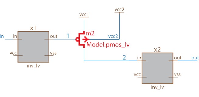
EOS occurs due to the existence of voltage differences across devices that exceed a threshold value. It typically results in varying degrees of performance degradation, including catastrophic damage where the IC becomes permanently non-functional [6]. Figure 2 shows a device-level EOS condition in which the pins of a PMOS transistor are connected to different power domains. In this example, if vcc2 is tied to 3.3v, but the gate is connected to 1.8v (vcc1 = 1.8v), this combination creates oxide stress on the m2 gate—a subtle design error that will cause failure over time.
EOS checks ensure designers use specific device types that can handle such voltage differences without performance issues or failure within the technology-specified value for such device types.
Cross-power-domain checks
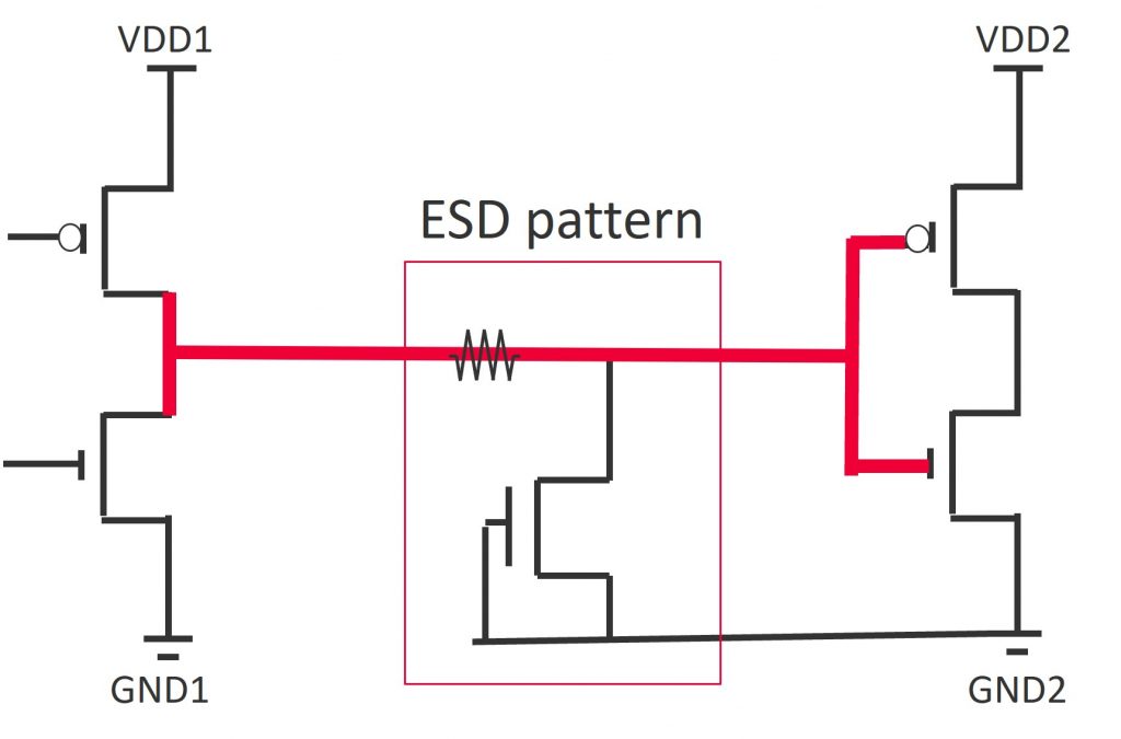
A crossing-power-domain condition occurs when a device is exposed to different power domains across its terminals. Cross-domain ESD protection is required to protect the different power domains from an ESD event crossing from one domain to another. For example, one commonly used ESD protection method is to connect a grounded-gate-NMOS (ggnmos) to the gate of the victim device (Figure 3). Checks that detect and verify accurate ESD protection for these cross-power-domain conditions are essential in multiple power domain SoC design verification.
Packaged checks simplify and speed reliability verification
Manually ensuring that all these cross-domain checks are properly set up and run can be time-consuming and error-prone, especially for today’s large, complex designs. To simplify setup and ensure accuracy and consistency, the Calibre PERC nmPlatform [5] provides pre-coded reliability checks that include the three categories of cross-power-domain reliability checks. The Calibre PERC packaged check framework permits simple selection and configuration of the pre-coded checks, maximizing ease-of-use and minimizing runtime setup. Designers can quickly and easily combine multiple checks into a single run for reliability validation of a design by leveraging this framework [6] [7].
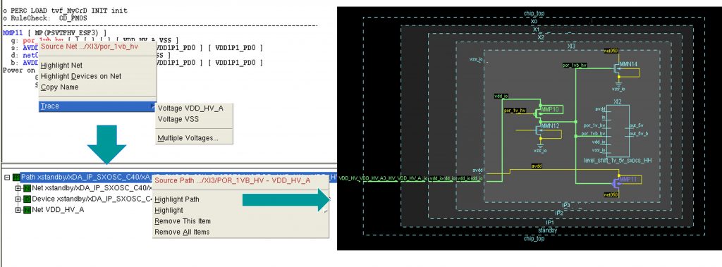
In addition, designers can easily debug and highlight error results using the Calibre RVE results viewer with its efficient tracing capabilities (Figure 4).

Figure 4. Highlight of a cross-power-domain violation where a gate is connected to one power domain, but the source/drain are connected to another power domain (Siemens EDA)
Conclusion
Multiple power domain designs add more complexity to reliability verification with the need to validate interactions between the different power domains and ensure adequate and accurate protection. To streamline cross-domain reliability verification, designers can use an automated reliability verification tool like the Calibre PERC reliability platform with its packaged checks flow to select and configure cross-power-domain, EOS, and level-shifter detection checks for their multiple power domain designs. Using a reliability verification tool with pre-coded checks ensures consistency and accuracy when running these complex checks on multiple-power-domain designs.
References
[1] Matthew Hogan, “Jumpstart your reliability verification with foundry-supported rule decks”, Mentor Graphics. https://resources.sw.siemens.com/en-US/white-paper-building-cmp-models-for-cmp-simulation-and-hotspot-detection
[2] Mentor, a Siemens Business. Mentor extends solutions to support TSMC 7nm FinFET Plus and 12nm FinFET process technologies, Sept. 13, 2017. https://www.prnewswire.com/news-releases/mentor-extends-solutions-to-support-tsmc-7nm-finfet-plus-and-12nm-finfet-process-technologies-300518633.html
[3] Mentor, a Siemens Business. Mentor Announces Availability of Tools and Flows for Samsung 8LPP and 7LPP Process Technologies, May 24, 2017. https://www.plm.automation.siemens.com/global/en/our-story/newsroom/mentor-availability-of-tools-flows-samsung-8lpp-7lpp-process-tech/91674
[4] Hossam Sarhan and Alexandre Arriordaz, “Automated Constraint Checks Enhance Analog Designs Reliability”, Mentor Graphics. https://resources.sw.siemens.com/en-US/white-paper-automated-constraint-checks-enhance-analog-design-reliability
[5] Siemens Digital Industries Software. “Calibre PERC reliability verification solution.” https://resources.sw.siemens.com/en-US/fact-sheet-calibre-perc
[6] Hossam Sarhan, “Configurable, easy-to-use, packaged reliability checks,” Siemens Digital Industries Software. March, 2019. https://resources.sw.siemens.com/en-US/white-paper-configurable-easy-to-use-packaged-reliability-checks
[7] Hossam Sarhan, “Complete reliability verification for multiple-power-domain designs,” Siemens Digital Industries Software. Sept. 2022. https://resources.sw.siemens.com/en-US/white-paper-complete-reliability-verification-for-multiple-power-domain-designs
 Hossam Sarhan is a senior product engineer in the Calibre Design Solutions division of Siemens Digital Industries Software, supporting the Calibre PERC reliability platform and Calibre parasitic extraction tools. Hossam received his B.Sc. from Alexandria University, Egypt, his M.Sc. degree from Nile University, Egypt, and his Ph.D. from CEA-LETI, Grenoble, France.
