P&R filler cell insertion slowing you down? Replace it
A physical verification-ready flow can speed project delivery by making your use of filler cells more efficient.
Time to market is a constant challenge. Time often equals profit, so the pressure to deliver a design to the foundry is very real, for both the design implementation and physical verification teams. At the same time, design quality is an essential element of market success. Designers cannot skimp on the processes that ensure their designs will achieve a profitable yield ramp and perform as intended. To that end, companies constantly evaluate their process flows and look for ways to reduce runtimes while ensuring design quality remains high.
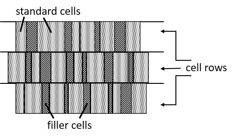
In the traditional design flow, the place and route (P&R) team implements the physical layout, then delivers it to the physical verification team. However, there has always been a time-sucking trap between those two steps. After P&R is complete, there are some open areas between logic cells that must be filled before physical verification can begin. P&R engineers typically use P&R tools to add filler cells—mostly non-functional cells that are used simply to continue the base layers as required for layer continuity and alignment, such as power/ground and Pwell/Nwell (Figure 1). In some cases, filler cells can also be decoupling capacitors (DCAPs) or engineering change order (ECO) cells.
Filler-cell insertion presents several issues that affect delivery:
- The insertion is a lengthy process, and both the design and filler cells must then be output to OASIS or GDS, which can also take hours.
- P&R tools use a limited set of design rule checks (DRC) that do not fully represent the foundry-qualified rule deck. This can lead to DRC errors that must be debugged during physical verification.
- The design itself may not support correct filler cell insertion (e.g., due to standard cell placement), creating even more DRC errors that must be debugged and corrected.
- The insertion must be repeated with every logic or timing change. If not, the DRC run generates a large number of errors that must be debugged.
Sensing a theme here? As you can imagine, after waiting for the insertion process itself to complete, all of this debugging and correction takes up even more valuable time. That is particularly frustrating in the case of DRC errors caused by the process itself. Some of these physical verification requirements are:
- Spacing and width rules, including both minimum and maximum values;
- Electrically correct Vt compliance rules; and
- Poly maximum spacing between different cells.
A PVReady flow to inform filler cell decisions
Of course, EDA companies are in the business of helping engineers produce better designs in less time. They constantly innovate and enhance their tools and processes to provide more efficient and more accurate results. One way to reduce physical verification time is to find ways to complete filler cell insertion in less time, with more accurate results.
In collaboration with their customers, Mentor, a Siemens business, explored the practicality of creating a flow that uses existing functionality in their design for manufacturing (DFM) tool to insert these filler cells, rather than using the P&R tool process. The Calibre YieldEnhancer SmartFill functionality delivers correct-by-construction fill solutions for multiple P&R tools, foundries, and technology nodes. Mentor used the Calibre YieldEnhancer SmartFill functionality combined with other Calibre YieldEnhancer capabilities (such as analysis-based layout modification) to create the PVReady flow, a solution that delivers correct-by-construction filler cell insertion while integrating seamlessly with both P&R and physical verification tools.
After placement and routing is complete, the DEF/OASIS/GDS design database is generated without filler cells. Designers use the Calibre YieldEnhancer PVReady flow to read in the design database and perform correct-by-construction filler cell insertion based on foundry-qualified Calibre rule decks. The input design database is then merged with the filler cell data so physical verification can begin. Incremental DEF files are generated for the added cells to allow the results to be back-annotated into other design databases.
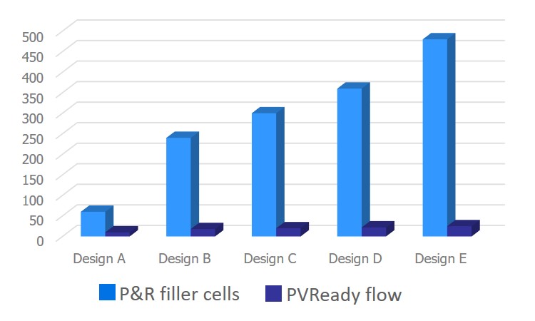
Using the Calibre YieldEnhancer PVReady filler cell insertion flow results in significant runtime reductions compared to P&R tool insertion. In tests run with multiple foundries and technologies, results yielded a consistent runtime that was essentially independent of the design size, generating anywhere from a 6-16x reduction in runtime per design iteration (Figure 2).

Figure 2. The Calibre YieldEnhancer PVReady filler cell flow provides significant runtime reductions regardless of design size (Mentor)
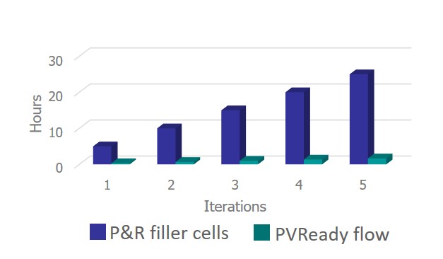
On average, the PVReady flow makes the design available for physical verification within 20 minutes of providing the P&R data in the OASIS/GDS/DEF format, compared to 4-6 hours typically required by a traditional P&R filler cell insertion flow. And, because filler cells must be placed after each ECO (both logic and timing changes), the savings in runtime provided is additive for each iteration through the design flow, resulting in an even faster time to tapeout (Figure 3).
While the initial focus was the insertion of non-functional filler cells, with the goal of reducing turnaround time for the front-end-of-line (FEOL) timing closure loop, the PVReady flow was extended to include the insertion of both DCAP and ECO filler cells. Over the span of a design flow, reducing the time it takes to place filler cells while also producing a DRC-compliant and electrically correct layout not only enables designers to begin physical verification earlier, but also reduces the amount of DRC debugging required. This results in faster tapeouts and higher-quality designs.
Time-to-market is a critical commodity in the electronics industry. Replacing inefficient, imprecise processes with smarter, more accurate, and faster functionality can improve both the bottom line and product quality. Every design company constantly evaluates their design flow to identify opportunities for faster design development, implementation, and verification. Every EDA company constantly examines their toolsuite to recognize situations where innovative applications of existing technology can provide users with better results in less time. The Calibre YieldEnhancer PVReady filler cell insertion flow is a prime example of providing designers with the ability to use existing technology in new ways that eliminate time-consuming tasks without sacrificing design quality.
For more information, download our new whitepaper, ‘Reduce the Time Delay between P&R and Physical Verification’.
About the authors
Fady Fouad is a senior product engineering manager in the Design to Silicon division of Mentor. His primary focus is the development and enhancement of DFM tools and flows that analyze and improve the manufacturability of design layouts while enhancing process efficiency and accuracy. He received a BSc in electrical engineering and communications systems from Ain Shams University.
Esraa Swillam is a senior product engineer in the Design to Silicon division of Mentor, a Siemens business, supporting Calibre DFM products. She works with software engineering, product marketing, field engineering, and customers to define and characterize new tools and capabilities. Esraa received her BSc in Electrical Engineering from Ain Shams University, and an MSc in Electronics Engineering from the American University in Cairo.
Jeff Wilson is a product management director for DFM applications in the Calibre organization at Mentor, a Siemens business. He is responsible for the development of tools and functionalities that analyze and modify layout. Jeff previously worked at Motorola and SCS. He holds a BSc in design engineering from Brigham Young University and an MBA from the University of Oregon.


