PID yield loss countered by path-based antenna verification
Plasma induced damage (PID) in gate oxide is a threat to MOSFET circuit yield and reliability. How can you effectively combat this issue?
As an IC (integrated circuit) chip designer, you are constantly striving to meet ever-increasing standards of reliability and performance in the fast-paced realm of semiconductor design and manufacturing, right? Amidst the challenges you face, plasma induced damage (PID) in gate oxide, often referred to as the antenna effect, stands as a significant threat to MOSFET circuit yield and reliability. How can you effectively combat this issue? The answer lies in combining traditional design rule checking (DRC) with an innovative path-based verification technique within your EDA workflows. Let’s explore the advantages of path-based antenna verification and discover how this approach navigates intricate antenna design rules and contributes to the enhancement of chip reliability.
Traditional antenna design rules
Before we get into the details, it’s essential to understand traditional antenna DRC. Typically, these checks perform checking layer-by-layer for the maximum allowed area ratio between a metal (or via) layer and the MOSFET gate layer connected to the same net, as shown in Figure 1(a). The addition of a diode protection device can expand this maximum allowed area ratio, as shown in Figure 1(b). Traditional DRC antenna checks efficiently handle these rules.
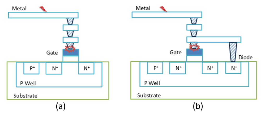
Figure 1. Traditional antenna design rules check for area ratio between metal (or via) layer and MOSFET gate layer (a) without protection diode, and (b) with protection diode (Siemens EDA)
Evolving challenges in IC chip design
In recent years, analog mixed-signal (AMS) designs have gained popularity due to their compact integration and reduced power consumption. AMS designs include multiple power domains, leading to cross-domain design challenges. These challenges include the existence of isolated P-type wells, introducing new types of antenna issues. Traditional DRC-based checks alone cannot effectively address these complex conditions. So, what do we do?
Path-based antenna verification
The solution to overcoming these new antenna conditions is a path-based verification approach that considers device interactions and encompasses various verification scenarios, such as risk connections, charging damage, connectivity waivers and unintended protection diodes. Let’s look at each in turn.
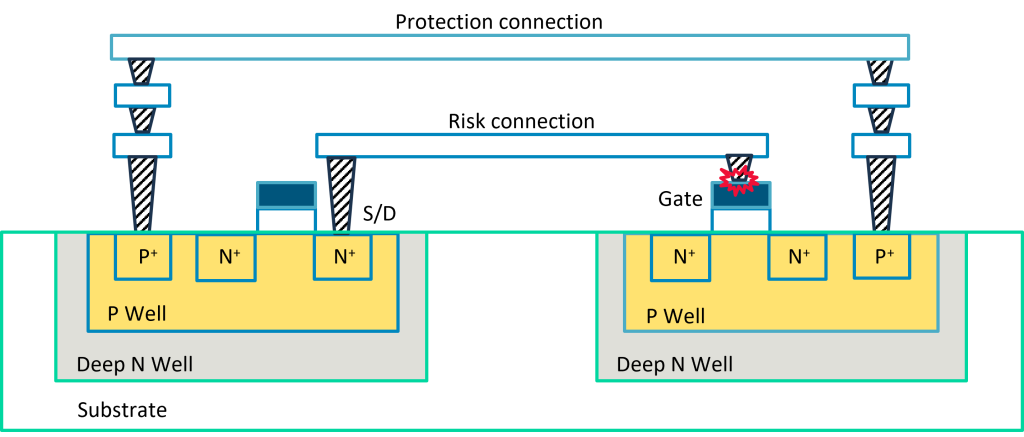
Risk connections: Identify connections between a driver and receiver before the corresponding protection connection is established, as shown in Figure 2. Antenna design rules check for and flag violations when a risk connection between driver and receiver is established before corresponding protection connection between the two isolated P-type wells is established
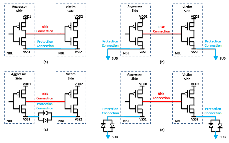
Charging damage: Detect imbalanced area ratios between metal (or via) layers and well layers from two isolated P-type wells, as shown in Figure 3 [4]. Antenna design rules check for charging damage induced by imbalanced area ratios between metal (or via) layers and well layers from two isolated P-type wells.
Connectivity waivers: Analyze complex connectivity conditions that can waive antenna violations caused by imbalanced area ratios, as shown in Figure 4 [4]. Connectivity conditions can be used to waive antenna violations caused by imbalanced area ratios between metal (or via) layers and well layers from two isolated P-type wells
Unintended protection diodes: Check for unintended protection diodes formed due to connectivity, which increases the maximum allowed area ratios, as illustrated in Figure 5. It shows where an unintentional protection diode is formed due to a protection connection between two isolated P-type wells, which will increase the maximum allowed area ratio between any same-level or higher metal (or via) layer and MOSFET gate layer
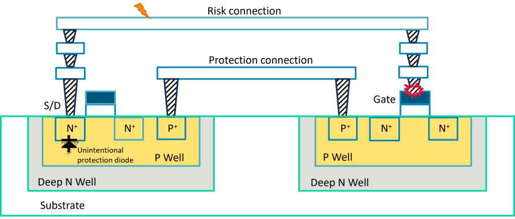
Figure 5. An unintentional protection diode is formed due to a protection connection between two isolated P-type wells (Siemens EDA)
Calibre PERC platform: Automated path-based verification
Addressing these complex antenna design rules requires a verification tool that understands devices, connectivity, and electrical paths within IC chip designs while calculating metal and MOSFET gate layer areas. The Siemens EDA Calibre PERC reliability verification platform allows designers to identify paths of interest in IC chip designs and can perform intricate rule checks on those paths, offering flexibility, efficiency, and accuracy in complex antenna verification.
Path-based PID verification flow
The Calibre PERC path-based PID flow begins by performing layout vs. schematic (LVS) device extraction to identify nets and devices. It then traces topological paths to identify aggressor and victim devices, risk connections, protection connections, and waiver conditions specified in foundry PID design rules. Based on this information, the tool performs area calculations and flags victim MOSFET gates with connections that do not meet area ratio requirements. Figure 6 shows a flowchart of the Calibre PERC path-based PID flow.
Interpreting path-based PID verification results
Understanding the results of the Calibre PERC path-based PID flow are crucial for accurately identifying potential PID violations. Figure 7 shows two layouts displayed in the Calibre DESIGNrev layout viewer. Figure 7(a) illustrates a PID violation where a risk connection between an aggressor and a victim is established at the metal1 level before the corresponding protection connection between the two isolated P-type wells is formed at the metal2 level. In contrast, Figure 7(b) shows a layout where both the risk connection and the protection connection are established at the metal2 level, avoiding a PID violation.
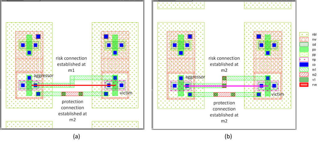
Figure 7. Viewing PID violations: (a) a PID violation is flagged when the risk connection from aggressor (S/D of NMOS) to victim (Gate of NMOS) is established at metal1 before the protection connection between the two isolated P-wells is established at metal2; (b) this layout does not create a PID violation, given both the risk connection and the protection connection are established at metal2 (Siemens EDA)
In Figure 8, PID violations caused by imbalanced area ratios between metal (or via) layers and well layers from two isolated P-type wells are viewed in the Calibre RVE results viewer, and highlighted in the Calibre DESIGNrev layout viewer. These results help designers debug and rectify potential issues promptly.

Figure 8. Debug of PID violations caused by imbalanced area ratios between metal (or via) layers and well layers from two isolated P-type wells: (left) Calibre RVE view of area ratios of metal and N-type buried layer (NBL) layers from aggressor and victim sides; (right) highlight of a NMOS gate (victim) that shows an area ratio violation in the Calibre DESIGNrev layout viewer (Siemens EDA)
Complementary verification flows
While the path-based verification approach is essential for addressing evolving antenna design rules, traditional DRC-based antenna checking remains valuable. These two verification flows complement each other, providing complete coverage of both traditional and evolving antenna design rules. During the early design stages, when connections are incomplete, DRC-based checks can be used for preliminary antenna-related correct-by-construction checking. DRC verification ensures that layouts are constructed with PID prevention in mind, reducing the need for time-consuming fixes in later iterations, as shown in Figure 9(a). As paths form across isolated P-type wells, the path-based solution becomes indispensable to check complex antenna design rules, as shown in Figure 9(b).
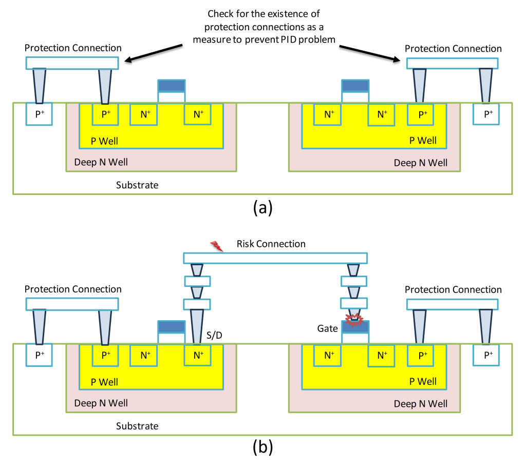
Figure 9. (a) When paths have not established, use DRC verification to perform preventative checks for a more robust layout design against antenna problems; (b) when paths are established, use the Calibre PERC path-based verification flow to check complex antenna design rules for signoff (Siemens EDA)
Summary
The ever-evolving field of IC chip design demands innovative solutions to address complex antenna design rules effectively. To meet this challenge, the Calibre PERC reliability verification platform offers a robust path-based verification approach that complements traditional DRC-based antenna checks. By using both verification techniques, IC chip designers can ensure the reliability and performance of their designs while significantly reducing PID risks during manufacturing. The production of high-quality IC chip designs is essential to meeting the demands of advanced semiconductor process nodes and ensuring continued success!
If you’d like even more details about path-based antenna verification, we dive deeper into this topic in our technical paper, Path-based antenna design rules reduce PID susceptibility in IC designs, on Siemens EDA.
References
- Watanabe, and Y. Yoshida, “Dielectric Breakdown of Gate Insulator due to Reactive Etching”, Solid State Technology, Vol. 26 (4) p.263, Apr. 1984.
- Shin, C. King and C. Hu, “Thin oxide damage by plasma etching and ashing processes,” 30th Annual Proceedings Reliability Physics 1992, San Diego, CA, USA, 1992, pp. 37-41, doi: 10.1109/RELPHY.1992.187618.
- Martin, “Plasma Processing Induced Charging Damage (PID) Discussion Group,” 2022 IEEE International Integrated Reliability Workshop (IIRW), South Lake Tahoe, CA, USA, 2022, pp. 1-11, doi: 10.1109/IIRW56459.2022.10032740.
- -L. Chu, et al., “New RC-Imbalance Failure Mechanism of Well Charging Damage and The Implemented Rule,” 2022 IEEE International Reliability Physics Symposium (IRPS), Dallas, TX, USA, 2022, pp. 8A.3-1-8A.3-4, doi: 10.1109/IRPS48227.2022.9764488.
- Yan, “Ensuring Robust ESD Protection in IC Designs,” Siemens Digital Industries Software, 2017. https://resources.sw.siemens.com/en-US/white-paper-ensuring-robust-esd-protection-in-ic-designs
About the author
Derong Yan is a principal product engineer in the Calibre Design Solutions division of Siemens EDA, a part of Siemens Digital Industries Solutions. His primary focus is the Calibre PERC reliability platform and reliability verification strategy. Areas of expertise include SoC physical design and verification, reliability verification, and design automation. Before joining Siemens, Derong worked for multiple semiconductor companies. He holds a Ph.D. in Materials Engineering from the University of Alberta, and received both his M.Sc. and B.Sc. from Shanghai Jiao Tong University.
