How MaxLinear got faster signoff DRC while optimizing reliability and manufacturability
The RF and AMS specialist turned to design software that allowed it to run design checks during place and route.
MaxLinear is a pioneer in low-power CMOS radio frequency (RF) and analog/mixed-signal (AMS) integrated circuits (ICs) for the connected home, wired and wireless infrastructure, and industrial and multi-market applications. Its digital signal processing (DSP) system-on-chip (SoC) solution tackles the high-speed optical interconnect needs of mega-scale cloud and enterprise data centers. These DSP chips for the server market are expected to work for 10 years or more, meaning both reliability and manufacturability are critical components of a successful design process.
Place and route (P&R) engineers at MaxLinear must pursue these goals while also optimizing their power, performance, and area (PPA) during layout implementation. Automated design enhancements during P&R often create layout variances that lead to complex design rule checking (DRC) errors at the chip level, such as top-level/intellectual property (IP) blocks interface problems, or ‘last mile’ functional/timing engineering change order (ECO) errors. The intricacy of these types of errors typically requires manual debugging and correction during DRC closure.
However, traditional batch DRC flows are set up for full-chip runs. They are not optimized to provide immediate DRC feedback on select design windows. In an effort to minimize debug time while ensuring correct-by-construction accuracy, P&R engineers at MaxLinear sought to optimize their digital implementation physical verification process by implementing Calibre RealTime Digital in-design DRC to enable on-demand Calibre signoff DRC within the P&R environment.
Design challenges and opportunities
MaxLinear’s chips contain analog and digital components. Because analog designs do not require many layers for routing connections, MaxLinear optimizes the number of layers available for routing. This helps reduce the overall cost of manufacturing.
However, by increasing routing density in all layers uniformly, this layer optimization can also increase the challenge of routing the digital designs, and typically means additional signoff DRC iterations are needed to achieve DRC closure.
Native P&R DRC engines are designed to fix most DRC errors, but the violations they do not address are typically those complex ones that require multiple manual debugging and DRC iterations to fix. This process can take weeks and potentially delay tapeout. After the fixes are made in a local window, designers must manually merge the P&R data with IP data to generate a merged GDSII/OASIS database, and then run full batch DRC to verify the fixes. If any DRC errors still exist, this time-consuming process must be repeated again and again.
The difficulty is compounded by the inability of the P&R DRC solutions to recognize and flag some types of DRC violations, such as those introduced by:
- Manual DRC error fixes
- Last-minute functional/timing ECO changes
- Final via swaps made to improve DFM scores
MaxLinear wanted a flow that improved DRC closure time while still delivering its design reliability and manufacturability requirements, as well as its PPA design goals.
The Calibre RealTime Digital interface provides direct calls to the Calibre analysis engines that run foundry-qualified signoff Calibre rule decks (Figure 1). These engines perform fast and incremental checks near shapes being edited and provide nearly instantaneous feedback on DRC violations. Immediate feedback within the P&R domain means that MaxLinear engineers can implement and check fixes with signoff quality, without the need for full DRC iterations. They can thus achieve shorter DRC closure cycle times while sticking to all design goals.
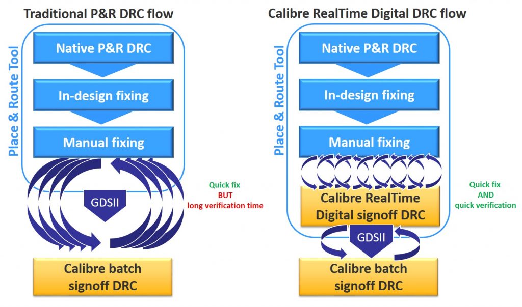
Figure 1. Traditional P&R DRC flow compared to the Calibre RealTime Digital in-design signoff DRC flow (Mentor)
Below, we review three areas where MaxLinear was able to improve design quality while reducing design closure time: via selection; multi-patterning (MP) error fixing; and last-mile DRC closure.
Via selection
One of MaxLinear’s design goals is a DFM via score of at least an 80 per cent. This challenging task requires engineers to implement the best type of via in a given design area that addresses timing, reliability, and manufacturability.
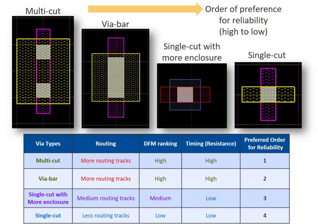
Foundries typically provide four types of via: single-cut; single-cut with extended enclosure; via-bar; and multi-cut (Figure 2).
Of these, the single cut is the least desirable because it has high resistance (negatively affecting timing), and a low DFM ranking is. However, it does make routing easier, which leads to fewer DRC errors.
Single-cut vias with additional enclosure space around the vias have a better DFM ranking, but also still have high resistance.
Via-bars offer a high DFM ranking and better timing (because of the decrease in resistance), but the routing is more challenging.
Multi-cut vias offer the best reliability because they have two via shapes (making it unlikely that the vias will fail during manufacturing), and have performance benefits compared to both single-cut via types. However, they pose the same routing challenges as via-bars.
During digital design implementation, MaxLinear’s prefers to maximize the use of multi-cut and via-bar vias to ensure that designs meet timing, reliability, and manufacturability requirements. However, both multi-cut and via-bar types make routing the design more challenging, creating complex DRC errors that typically must be fixed manually.
With Calibre RealTime Digital in-design DRC by contrast, engineers can swap in new via types, use its in-design DRC in a local window to catch any DRC errors created by the swap, apply fixes, and then quickly validate again to ensure the layout is DRC-clean. They can also recheck DFM scores after completing multiple via swaps, (typically when they are confident they are near or have achieved their target DFM score).
Multi-patterning errors
In addition to DRC errors, swapping out a single cut via for a multi-cut or via-bar via can cause multi-patterining (MP) violations (Figure 3). Given the complexity of MP spacing requirements, these errors can be particularly hard and time-consuming to fix. The solution to one error can often create another.
Engineers typically perform a ‘what-if’ analysis on the layout by performing a manual fix and waiting for the DRC feedback. With immediate signoff DRC feedback on each manual edit, multiple such analyses can be rapidly completed as needed. This helps P&R engineers quickly and confidently determine and implement the best fix for the MP violation.
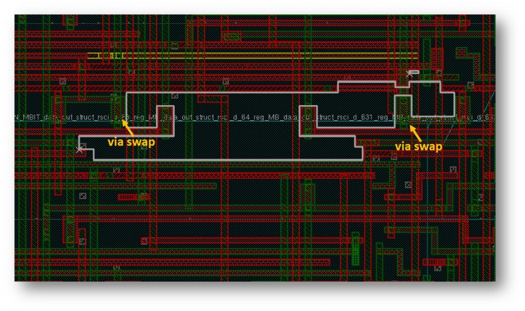
Figure 3. A single to multi-cut via swap causes an MP violation that can be manually fixed and immediately validated with signoff DRC confidence (Mentor)
Last mile DRC closure
A move to a more advanced technology node typically causes the area of standard cells to shrink by around 55%. However, the area of the wires shrinks by only around 30%. The resulting increase in pin density makes it difficult for the P&R routing engine to access the pins during routing without creating DRC errors. In MaxLinear’s case, this challenge was further complicated by the company’s wish to use a limited set of routing layers to reduce manufacturing costs, an approach that uniformly increases routing density across all layers.
During the last stages of DRC closure, there are specific issues that can benefit from the use of signoff in-design DRC.
Spacing violations
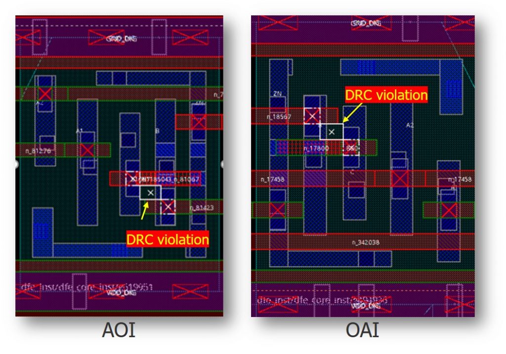
Diagonal via spacing violations can be created during routing to AOI and OAI cells (Figure 4).
To fix these types of spacing violations, designers must move vias while ensuring no new DRC violation is generated. Using the Calibre RealTime Digital interface to get immediate feedback on manual DRC fixes, MaxLinear P&R engineers were able to quickly implement an optimum fix, confident that they were not creating another DRC violation (Figure 5).

Figure 5. The Calibre RealTime Digital in-design DRC provides immediate signoff-quality feedback on placement violations for fast validation in the P&R environment (Mentor)
ECO errors
When a design is close to tapeout, functional or timing errors usually require an ECO adjustment to the layout, which can result in a signal short (Figure 6). P&R engineers have two options: they can implement another ECO, or fix the short manually. Applying another ECO modification can potentially affect the timing metrics of surrounding nets, as the router looks at the surrounding areas before making the required connectivity changes. For this reason, P&R engineers usually opt to manually fix the short to avoid any alteration to the surrounding nets. With the Calibre RealTime Digital interface, P&R engineers can manually fix the short in the P&R environment, and use the immediate DRC feedback to verify the fix.
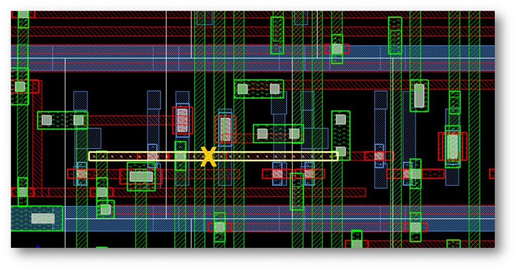
Figure 6. The signal short caused by an ECO adjustment can be manually fixed and then quickly verified in the P&R environment (Mentor)
Interface errors
In certain design conditions, an ECO change causes top-level and analog IP interface DRC errors. For example, tie-hi and tie-low signals are required in an IC, because not all inputs are used. To avoid glitches, unused inputs should be locked to a stable logic state, and not left floating.
As shown by the example in Figure 7, MaxLinear P&R engineers realized they had to connect the signal route to a pin in the analog IP that was originally a tie-low signal, which required a functional ECO (netlist change). This ECO change caused a DRC issue with the other port of the analog IP. The engineers determined the optimum fix was with a manual correction, using the Calibre RealTime Digital interface to immediately validate the fix and ensure no new DRC errors were generated.
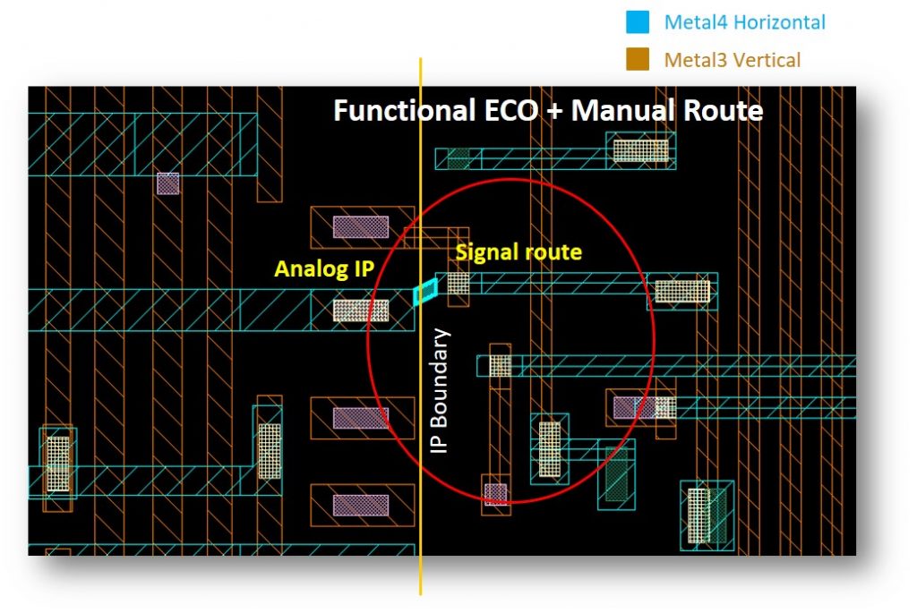
Figure 7. A functional ECO change resulted in a tie-low signal in IP being connected to top-level signal, creating IP/block interface DRC violations (Mentor)
Signal EM issues
Near tapeout, MaxLinear P&R engineers observed that the high-fanout and frequently switching nets (such as the clock net) were drawing excess current. This can lead to signal electromigration (EM) issues. On inspection, the engineers determined the clock net was drawing high current because the router had inserted single-cut vias (an EM violation) to avoid routability issues.
This EM violation did not extend across the entire net. Because a strong driver drives high-fanout nets, the EM violation only happens on the driver side, not on the receiver side. Fixing this violation requires careful inspection of the design to determine whether to swap the single-cut vias with multi-cut vias or via-bars, or to convert the single width wire to double width to drive more current (Figure 8). Once this design decision was made, the engineers used the immediate signoff DRC feedback from the Calibre RealTime Digital interface to validate the manual edits, helping them reach DRC closure quickly and efficiently.

Figure 8. EM issues created on the high-toggle clock net (red arrows) were fixed by swapping single vias with multi-cut or via-bar vias (Mentor)
Re-tapeout checks
Sometimes, despite your best efforts, additional ECOs are needed after you have sent your tapeout design to the foundry. When this occurs, the foundry requires special re-tapeout (RTO) checks before you deliver the design with the ECOs back to the foundry. These special checks must be run when the mask for the layer is already prepared, adding more constraints to the location of your geometries. Although tapeouts are typically done layer by layer, when these late ECO changes are made to metal layers, the foundry will require the design team to run the RTO checks on related layers as well. For example, if the ECO changes were on the Metal2 and Metal3 layers, designers would also need to run RTO checks on Via1 and Via3 layers.
The additional constraints imposed during RTO checks makes DRC error fixing complex, typically requiring many DRC iterations that significantly extend the time it takes to re-tapeout a design. MaxLinear’s P&R engineers used Calibre RealTime Digital to interactively verify their RTO DRC fixes, and were able to quickly deliver the design back to the foundry, resulting in direct cost savings. As shown in Figure 9, an ECO resulted in the vertical metal path moving to the left, creating via enclosure errors on a neighboring net, as the two signals are now closer to one other. These via enclosure errors are seen only when running the RTO checks. MaxLinear P&R engineers used the Calibre RealTime Digital in-design DRC to perform a quick what-if analysis on this design window and determine the optimum fix.
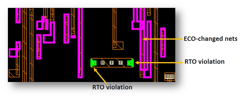
Figure 9. RTO via enclosure error created by ECO change after initial tapeout of specific design layers (Mentor)
MaxLinear results
The Calibre RealTime Digital interface enables P&R engineers at MaxLinear to perform targeted, on-demand Calibre signoff DRC during the digital design flows. To date, it has allowed them to meet unique timing, reliability and manufacturability constraints, while saving 50% over the previous physical verification closure time required for every design iteration across established and advanced process nodes (Figure 10).
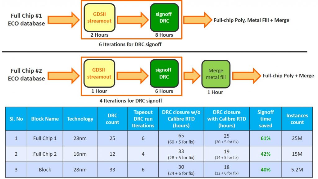
Figure 10. Runtime statistics demonstrate the benefits gained by using Calibre RealTime Digital in-design DRC at MaxLinear (Mentor)
In addition to the runtime benefits, having immediate Calibre signoff DRC feedback means MaxLinear digital designers can quickly explore the effect of new or revised design rules in new technology nodes. No more tedious design rule interpretations—designers can simply run a rule and immediately see the impact, enabling MaxLinear to more quickly implement new designs and get them to market.
Conclusion
Adopting the Calibre RealTime Digital interface enabled MaxLinear designers to accelerate DRC closure and save weeks in tapeout schedules for all designs at all nodes. By enabling fast, iterative signoff DRC checking and fixing during floorplanning and placement, the Calibre RealTime Digital interface not only reduces batch DRC iterations, but also eliminates late-stage issues during final physical verification signoff that are exponentially harder to fix. The immediate DRC feedback provided by the Calibre RealTime Digital interface supports a correct-by-construction approach, while enabling digital designers to better focus on meeting their power, performance, and area (PPA) goals. Because the full range of Calibre physical verification capabilities is available, users can interactively explore the cause of a DRC error and perform what-if analysis to determine the optimum fix. Eliminating the need for multiple database stream-outs and batch DRC runs provides significant productivity advantages for ‘last mile’ manual DRC closure, enabling digital designers to shave weeks off tapeout schedules. The Calibre RealTime Digital interface is built to let designers drive DRC closure, not tools.
For companies like MaxLinear sees these capabilities as contributing towards its an ability to satisfy the needs of mega-scale cloud and enterprise data centers. In this space, reliability and product life are a big part of making the difference between just being in the market, and being a market leader.
Further reading
Get more information by visiting the Calibre RealTime Digital product page, or download this whitepaper.
About the author
Srinivas Velivala is a product manager with the Design to Silicon division of Mentor, a Siemens business, focusing on developing the Calibre RealTime interface and other Calibre integration and interface technologies. Before joining Mentor, he designed high-density SRAM compilers. In addition to more than 12 years of design and product marketing experience, Srinivas holds a B.S. and M.S. in Electrical and Computer Engineering.
