Improve custom/AMS design and productivity with in-design DRC
In-design DRC is a technique that frees up engineers from many of the challenges of delivering AMS design under ever more complex design rules.
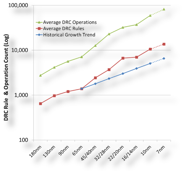
As every IC designer knows, layout design verification gets exponentially harder with each process node. New manufacturing constraints, such as multi-patterning, impose new layout requirements, while the number and complexity of design rules increases to account for new issues or ones that become significant (e.g., on-grid, pitch, and lithography alignment; complex line-end spacing conditions; and multi-dimensional effects. At 28nm and below, layout-dependent effects (LDEs) become critical, and advanced techniques, like using local interconnect layers to achieve dense local routing before the first metal layer, introduce new layout constraints. The result is that there are ten times more checks at 14nm than there were at 28nm. In fact, since 40nm, the industry has been increasing design rule check (DRC) count on average by 20-30% every node (Figure 1). Similarly, the complexity of each check has also increased node-over-node alongside the greater complexity of each process.
The overall impact has been particularly hard on custom and analog/mixed-signal (AMS) layout. Designers there must learn and understand progressively more complex DRC and layout limitations while striving to meet delivery schedules. They often find themselves fixing one DRC violation while creating another simultaneously, something that is not apparent until after the design database stream-out and batch DRC run.
With so many new rules, coupled with the complexity of their implementation, custom and AMS designers can no longer rely solely on their memory to avoid creating design rule errors in layouts. In addition, running DRC outside the design environment is no longer the best option, because designers cannot afford to wait for even one to two minutes to verify a single DRC fix on an area that only has 5-10K shapes. Most of this time is spent invoking the verification infrastructure, streaming out the database, and compiling the DRC deck, whereas the actual runtime of the DRC engine is less than two seconds. But what is the alternative?
How about in-design, real-time DRC? In-design DRC solutions perform fast, incremental checking in the vicinity of shapes being edited, providing near-instantaneous feedback on design rule violations, as well as information on other issues, such as systematic variation susceptibility. If designers receive immediate signoff DRC feedback on a layout configuration, they have more time and freedom to optimize and improvise, enabling them to improve the quality of their layouts while also maintaining (or even reducing) their tapeout schedules. Some advantages of in-design DRC include:
- Learning new technology requirements as you design;
- Performing ‘what-if’ analyses to optimize error fixes and layout adjustments as you design;
- Eliminating or mitigating layout-dependent effects quickly and accurately;
- Running multiple rule decks simultaneously;
- Debugging full-chip DRC errors more quickly;
- Grouping specified rule checks into ‘recipes’ for greater efficiency; and
- Automatically switching between in-design DRC and batch DRC as needed.
Learning new rules
In-design DRC helps eliminate the tedious task of interpreting new and modified design rules before using them. Instead, designers can quickly run multiple iterations of layout geometries to understand how complex rules affect and control design layouts. This ‘on-the-job’ learning provides faster understanding of the practical impact of rule changes. That can lead to better design optimization earlier in the design process, as well as a more uniform level of knowledge across a design team.
What-if analysis
Multi-patterning checks
Multi-patterning errors often have multiple solutions. In particular, multi-patterning rule checks often generate odd loop violations that require some what-if analysis to enable designers to evaluate potential fix options and apply the optimal fix. In addition, some fixes may create new errors. Obviously, attempting a what-if analysis with batch DRC requires multiple DRC runs, meaning more time. With tight tapeout schedules, designers may end up settling for a DRC-compliant, but less-than-optimal result. Because in-design DRC provides instantaneous feedback, designers can use it to evaluate and compare each possible fix quickly, without having to sacrifice quality enhancements. Additionally, depending on their multi-patterning technology, designers can take advantage of in-design DRC error analysis to avoid propagating additional multi-patterning errors while implementing a fix (Figure 2).

Figure 2. In-design DRC with multi-patterning error analysis quickly compares fix options while avoiding propagation of new errors (Mentor)
Area optimization
Area optimization is critical in designs at advanced nodes, such as high-density memory compilers with their increasing demand to pack more storage capacity in smaller sizes. Such dense design layouts require a thorough knowledge of the design rules. That is a challenge for individual designers. But an in-design DRC solution can perform all checks that can be run with the DRC tool (including functionality such as recommended rules, pattern matching, equation-based DRC, and multi-patterning). In-design DRC allows custom/AMS designers to try out different widths and spacings in a layout editor to reach the best area optimization (Figure 3). The quick feedback from the in-design DRC process allows designers to evaluate multiple DRC fixes, without having to wait for a stream-out and DRC run for each option. With in-design DRC, designers can correct and adjust their work during the layout process to produce a DRC-clean design that is resistant to manufacturing variability issues and optimized for the most desirable performance and operational characteristics.
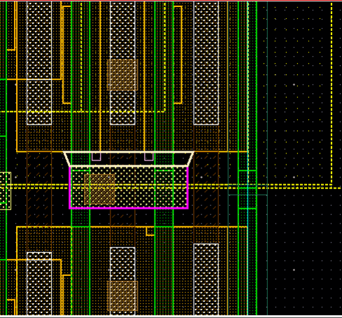
Figure 3. In-design DRC enables fast comparisons so designers can optimize area quickly and efficiently (Mentor).
Design reviews
In-design DRC can assist in the review of a block – for example, where there are concerns about IR issues for certain regions and layers. Since IR drop is dependent on the resistance of wires in a net, increasing wire width is one of the design options available to eliminate problems. Of course, changing width and spacing between wires can create DRC violations. To mitigate these concerns, designers can perform on-the-spot what-if analysis editing with in-design DRC. They can thus try different scenarios to see where wire widths can be increased without generating DRC errors. This type of review helps them quickly find the best solution and alleviates concerns about potential layout issues (Figure 4).
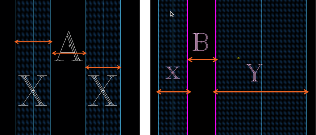
Figure 4. Perform what-if analysis with in-design DRC to fix issues like IR drop by changing the width of metal layers until they reach their optimum (Mentor).
Layout-dependent effects
Layout-dependent effects (LDEs) are highly important in custom and AMS design. At advanced nodes, back-end-of- line (BEOL) DRC clean-up is crucial to device performance, and fixing these DRC errors optimally is a critical task. For example, the introduction of double dummy poly, and the continuous running of poly with poly cut layers wherever a poly break occurs, instituted a host of new design rules. Middle-end-of-line (MEOL)/local interconnect layers add further complexity to the design rule checks. To fix LDE errors, such as double dummy poly errors that involve base layer edits, in-design DRC can be used directly in a layout editor (Figure 5).
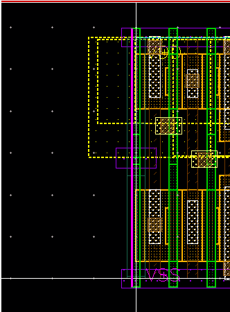
Figure 5. Double dummy poly errors (purple highlight) can be identified and corrected in a layout editor using in-design DRC (Mentor)
Running multiple rule decks
Custom/AMS designers often face a dilemma when running DRC. They must verify their designs against the signoff design rule deck — the deck supplied by the foundry — but must also run one or more internal rule decks for company-specific design constraints. For example, a foundry signoff deck typically does not include recommended rule checks, but a design company may require such checks to ensure their designs are optimized for manufacturing. Similarly, foundry multi-patterning checks only highlight the actual multi-patterning errors they identify in a layout, but debugging these errors can be tricky. Running a multi-patterning deck that includes auxiliary error information can help designers debug multi-patterning errors more quickly and efficiently. Running multiple decks sequentially is time-consuming, and debugging is equally tedious because the designer must wait for each results list to be compiled. In most cases, the ability to automatically run a design against multiple decks will improve productivity significantly, but only where designers can easily switch between the decks without delays. To ensure custom/AMS designers have maximum flexibility to work in their preferred styles, some in-design DRC solutions allow them to decide whether to switch between rule deck runs manually, or to select multiple rule decks and allow them to automatically run simultaneously. When multiple rule decks are run, error results must be identified by the rule deck that generated the error, so designers can make quick decisions about priority fixes.
Debug full-chip DRC errors
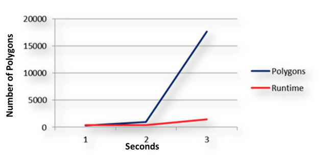
During the tapeout phase, designers often encounter last-minute violations in their batch DRC flow. An in-design DRC solution allows them to quickly load the design, edit the problem polygons, and verify the changes on-the-fly. The in-design DRC process ensures that the DRC cycle will converge. This approach also reduces the number of batch DRC iterations and overall cycle time. Figure 6 displays an example of this runtime scaling with a large number of geometries using the Calibre RealTime in-design DRC solution and the Calibre DESIGNrev layout editor. For this design, typical runtime results are represented by these measurements:
- TOTAL CHECK COUNT = 2555
- TOTAL RESULT COUNT = 261
- TOTAL ORIGINAL GEOMETRY COUNT = 17645
- TOTAL RUNTIME = 1478.046ms
Check recipes
Some in-design DRC solutions support a verification technique called ‘check recipe’. It allows designers to run only those checks they are interested in for a particular project task, rather than generating all DRC errors from the entire rule deck. As well as enabling the creation of custom rule groups, check recipes also provides access to pre-defined foundry deck check groups. Check recipes prevent unrelated error markers from overloading the layout design window and distracting designers by showing them all the signoff DRC errors that they are not interested in fixing at that particular moment. For example, designers can use check recipes to run node-specific checks, such as odd-loop and layout-dependent checks. The odd-loop recipe selects all the odd-loop checks by looking for the pattern *odd cycle* in the comments of the rule check. Check recipes can also be used to exclude certain checks. For example, when working on a cell design layout, designers can use a check recipe to turn off the full-chip density and antenna checks generating DRC violations that are irrelevant until the cell is placed in the larger design. In short, check recipes help designers focus on the job at hand, and improve productivity by eliminating distractions.
Productivity enhancements
Because in-design DRC provides so many benefits, designers often want to run it on everything. But it was never designed to replace a full signoff DRC run. In-design DRC is typically for use on cell/block layout designs, not an entire design. Trying to exceed the capacity of an in-design DRC solution reduces its efficiency. The value of using in-design DRC in place of a batch DRC run vanishes. However, to better bridge the gap between cell/block verification and macro/full chip design verification, some in-design DRC solutions automatically enable batch DRC when the designer exceeds the user-defined verification limit. These solutions can seamlessly and automatically determine when to launch a batch DRC job. Results are imported back into the in-design DRC interface, so it recognizes both error results and the fixes made in the design layout. Typically, designers can use this option to run DRC on macros exceeding the use limitation, and still get the immediate DRC feedback when fixing errors. With this capability, the in-design DRC process can be used on a significant portion of a design. Only when designers are close to tapeout, which is when design sizes become really big, does it become necessary to use the signoff DRC flow.
Summary
In-design DRC helps custom/AMS designers manage the increasing complexity and number of DRC rules by providing immediate feedback that allows them to focus on creating better layouts in less time. Designers can concentrate on creating the best design possible by spending more time on layout creation and optimization, instead of waiting for and wading through results from full batch DRC runs. They get immediate feedback while editing edit the layout, ensuring DRC-clean, optimized custom designs in the shortest time possible. If the in-design DRC solution uses the same foundry-qualified rule decks and DRC engine used by the batch signoff platform, designers can fix a wide range of errors with signoff confidence. Using the fast response time of in-design DRC lets designers compare multiple layout options quickly, which allows designers to experiment to quickly and easily understand the impact of new or expanded design rule constraints. Continuous innovations such as in-design DRC are critical to ensuring custom/AMS designers continue to produce high-quality designs that provide all of the functionality and performance demanded by leading-edge electronics. Without constant creativity and innovation in their toolsets, designers face a much more difficult path in trying to implement and verify today’s complex layouts.
About the author
Srinivas Velivala is a Product Manager with the Design to Silicon Division of Mentor, a Siemens Business, focusing on developing Calibre RealTime and other Calibre integration and interface technologies. Before joining Mentor, he designed high-density SRAM compilers, and has over 10 years of design and product marketing experience. Srinivas holds a B.S. and M.S. in Electrical and Computer Engineering.
