Enhanced model-based hinting may be the edge you need below 20nm
A detailed dive into how MBH strategies for litho hotspots have been enhanced to deal with double patterning at 20nm and below.
Before accepting a design for manufacture, a foundry typically requires a wide range of verification checkpoints beyond just the basic design rule checking (DRC) signoff [1][2]. One of those is a lithographic (litho) process verification for standard cells and design-specific intellectual property (IP) blocks. This verification incorporates both mandatory DRC and design for manufacturing (DFM) recommended rules to find and fix potential litho failure points (hotspots) in the layout prior to manufacturing. However, while fixing these hotspots, the designers must be careful not to unintentionally introduce new hotspots. Unfortunately, because most designers do not have an in-depth understanding of all the non-linear complex steps that a layout undergoes during manufacturing, this hotspot fixing can be quite challenging.
At Mentor, we responded to this challenge by adding a model-based hinting (MBH) functionality to our litho checking tools. It provides repair hints to the designer: recommendations for design layout changes that would fix the hotspot. A typical repair hint starts with a list of candidate edges that could be moved to avoid or eliminate the hotspot. For each candidate, the tool performs some basic DRC (such as minimum spacing or width) to define the recommended movement in the form of direction and value. The engine then tests each candidate by implementing the movement in a generated layout clip and analyzing the result. If the clip is free of litho hotspots, the candidate hint is added to the list that is presented to the designer [3]. MBH functionality made litho hotspot fixing much easier and faster, because it covertly supplied much of the deep knowledge needed to make intelligent fixing choices.
This MBH approach worked well until the introduction of double patterning at the 20nm design node. Double patterning required multi-layer, multi-mask design rules to ensure manufacturability; existing MBH solutions typically performed DRC only on the layers that contained a hotspot. At the same time, sub-20nm scaling resulted in a significant increase in design rules that were often too restrictive to guarantee a litho/etch hotspot-free design. To make matters worse, the congestion of sub-20nm layouts further reduced the chances of finding a valid hotspot fix.
Confronted with these challenges, we have responded with a new approach to MBH fixing. We extended the DRC rules to include multiple-layer DRC checks and rules for different masks. With these extensions, MBH can now evaluate DRC across layers, meaning it can now recommend moving not just a group of edges, but complete metal polygons (including any enclosed via). This enhanced MBH solution can now take into consideration enclosure rules between metals and vias or contacts, enabling more accurate fixing suggestions.
To show you how this enhanced MBH functionality works, let’s look at some typical situations.
Surrounding wires spreading
Traditional MBH is based on individual local optimizations around the hotspots, such as moving a single corner, a single line end, or the hotspot’s adjacent edges. At 20nm, these types of optimizations are often restricted due to the strict design rules applied to these congested designs.
Enhanced MBH uses an algorithm to identify a set of wire spreading candidates around the litho hotspot that can be adjusted if the single local optimization is not practical. This algorithm can move entire polygons instead of just single or dual edges (like corners). However, these movements can affect the circuit connectivity. To avoid this impact, MBH users define a set of rules that maintain the circuit connectivity, DRC-clean layout, and DP coloring.
Enhanced MBH starts with a hotspot and its adjacent edges, corners, or line ends. Each of these is a candidate whose movement might eliminate the hotspot. The algorithm (for wire spreading mode) operates in the following manner:
- MBH sorts the candidates in ascending order, based on their distance from the hotspot center.
- MBH runs iteratively through the candidates; each iteration should generate a hint that can possibly eliminate the hotspot.
- For each iteration, MBH chooses one candidate to move. If this candidate moves, MBH adds the movement to the set of wire spreading candidates and jumps to the next iteration.
- If the chosen candidate does not move (because of design or rule restrictions), MBH moves the opposite edge or set of edges of the target layer(s) until the candidate moves or nothing can be moved further. These edges are added to the set of wire-spreading candidates.
- Once the set of candidates is complete, edges are moved to determine which outputs do not violate DRC rules, while ensuring that the existing electrical connectivity and/or DP coloring are maintained.
- The outputs that satisfy all these conditions are presented to the user as possible solutions.
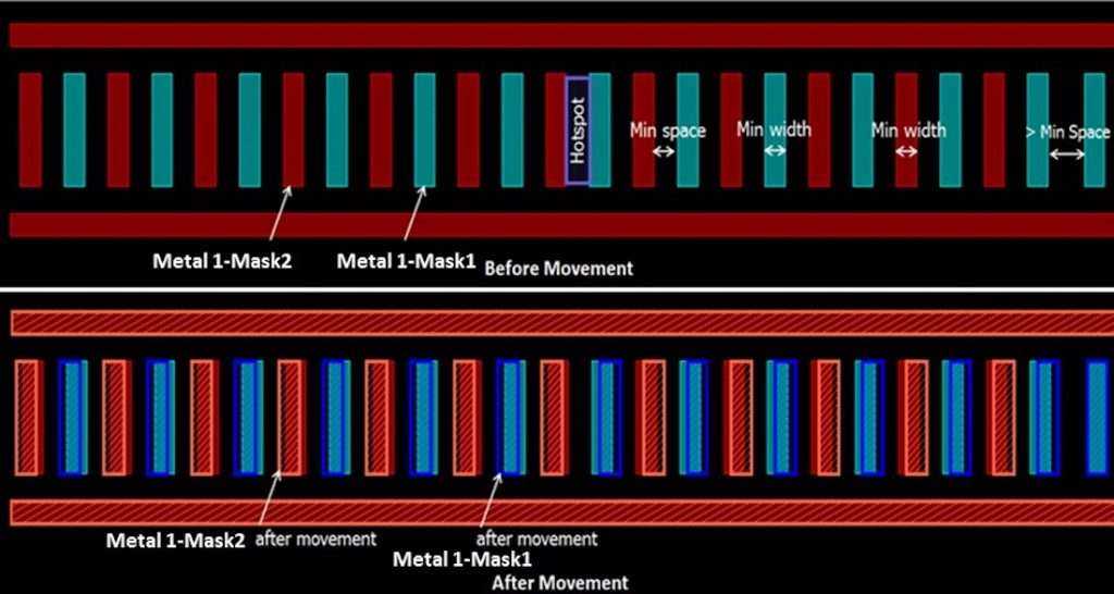
Figure 1 shows a congested DP design clip with free spaces only near the edges of the clip. The target layer is the DP metal layer (i.e., Metal_Mask1 and Metal_Mask2). The generated solution by MBH pushes the DP layer polygons on the left of the hotspot to the left, and those on the right of the hotspot to the right, keeping it DRC and DP-coloring clean. In this example, electrical connectivity is not an issue, because there are no vias.
Multi-layer movement along a layers stack
Sometimes, because of DRC and DP coloring restrictions, certain movements are not allowed, as they will break the specified constraints between layers. In enhanced MBH, the wire-spreading algorithm is extended to allow multiple layers to move. This enhancement allows wires to spread away from hotspots while preserving the design’s connectivity, and respecting DRC or DP coloring restrictions.
When analyzing multi-layer movement, the MBH algorithm performs the same way it did for wire spreading, except it now also takes into account circuit connectivity rules. If the movement is forbidden due to circuit connectivity violations, the algorithm moves both the blocking layer’s edge/polygon and the set of wire spreading candidates.
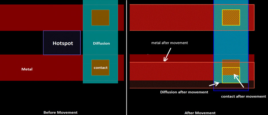
Figure 2 shows a hotspot between two metal edges, which identify the target layer. The algorithm cannot move just the lower touching edge away from the hotspot, because of the connectivity specified between the metal and diffusion, while moving the lower contact and the metal layer’s edge violates the enclosure rule specified between the contact and diffusion. In this situation, the solution found by enhanced MBH suggests moving three layers (metal, diffusion, contact), which eliminates the hotspot while maintaining the connectivity and keeping the design DRC-clean.
Model-based stitch and inter-mask bridge control
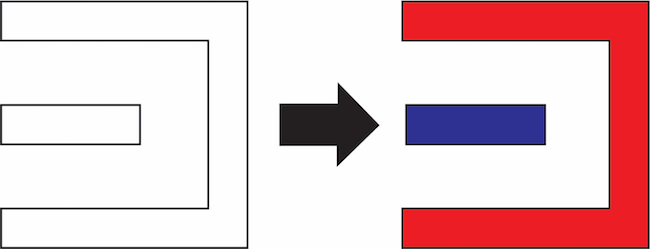
The double patterning methodology was developed to avoid process deformation caused by lithography limitations. DP design requires splitting (decomposing) the layout between two masks, so near-by polygons can be placed on different masks, as shown in Figure 3.
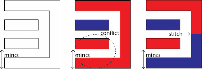
Of course, in actual layouts, the coloring process is not nearly as simple. Design complexity often creates conflicts where minimum coloring spacing (minCS) is violated. One common DP solution used to resolve these conflicts is stitching, which ‘divides’ a polygon into two differently- colored sections, as shown in Figure 4 [4].
The added stitch is considered an overlap area between the two masks. Because DP rules require that this overlap area must satisfy minimum values for both length and width (Figure 5), enhanced MBH must ensure that all candidate fixes comply with these minimum values.
Double-patterning design checks
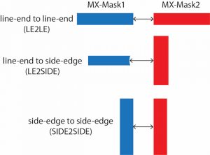
Because the two DP masks can have multiple possible orientations, special spacing rules (LE2LE, LE2SIDE & SIDE2SIDE) apply between the masks, as shown in Figure 6. Enhanced MBH verifies rule compliance before generating the candidate hints, to ensure the suggested fix remains DP-compliant. By avoiding the introduction of any coloring conflict, the need to re-color the design is eliminated.
Enhanced MBH in practice
We conducted experiments using 14nm and 20nm designs to test our enhanced MBH solution against various real-world conditions.
The first experiment (Figure 7) illustrates the difference between traditional MBH solutions, which only consider single layers, and the enhanced MBH solution that takes into account multiple-layers DRC rules before generating the candidate hints. On the left, traditional MBH considers only the DRC rules of metal1, which can easily create a contact enclosure violation. Using enhanced MBH, which extends the rules to include the contact enclosure, can avoid such violations, as shown on the right.
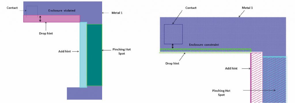
Figure 7: On the left, the drop polygon hint based on single layer DRC violates the enclosure constraint. On the right, the drop polygon hint is based on multiple-layers DRC, which allows the MBH engine to suggest an adjustment that complies with the enclosure constraint (Mentor – click to enlarge)
A second experiment tests the algorithm for spreading the metal wires (metal1 and metal2) away from a hotspot. In Figure 8, the enhanced MBH engine finds spacing in both the outer right and left-hand sides by spreading the polygons to eliminate the hotspot. The suggested hint moves the enclosed vias within the enlarged polygons.
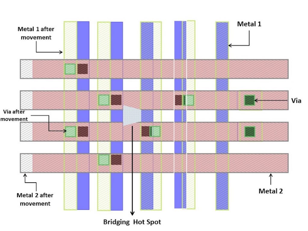
Figure 8: A multi-layer movement hint suggestion to eliminate the bridging hotspot (blue=metal1, red=metal2, black=via) (Mentor – click to enlarge)
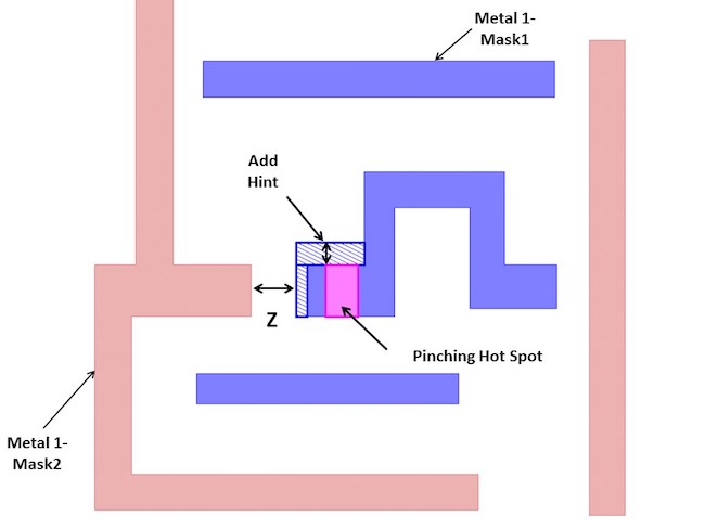
This multi-layer technique also provides appropriate hints for the stitching rule. As shown in Figure 9, a layout clip includes a pinching hotspot located inside a stitching area. The enhanced MBH engine provides a hint to push the stitch’s left edge (by adding a polygon hint) away from the hotspot. The MBH algorithm can apply a constraint that controls the stitch’s length based on its width, keeping the fix DP-compliant.
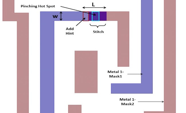
Figure 9: A pinching hotspot occurring on the DP stitch is eliminated by pushing the stitch edge outwards (Mentor)
In double-patterning designs, enhanced MBH can provide candidate hints that simultaneously consider different DRC rules for the two masks. As shown in Figure 10, the enhanced MBH engine complies with different DP DRC rules between masks in the same hint. In this example, space ‘H’ is bigger than space ‘K’, meaning the MBH engine can apply different values to the DP edge-to-edge DRC rule than those used for the DP edge-to-line-end DRC rule.
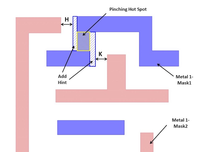
Figure 10: The enhanced MBH engine can apply hints that satisfy different DP constraints (edge-to-edge and edge-to-line-end) for each mask (Mentor)
Figure 11 shows what happens when a value is provided for the line-end-to-line-end DRC rule. The enhanced MBH engine ensures that the specified space of value ‘Z’ is satisfied between the two masks of the metal layer.
Summary
Layout congestion, tight spacing, and double-patterning constraints in sub-20nm designs pose new challenges for automated MBH tools. New algorithms that can consider DRC between different layers, enclosure rules between metals and vias or contacts, and complex DP spacing constraints enable more accurate analysis, while adding more flexibility to generated hints.
Our experiments demonstrate that an enhanced MBH engine can dramatically speed up the typical manual fixing flow that uses several iterations of incremental LFD simulation to clear litho hotspots.
Adopting an enhanced MBH flow can help design companies deliver sub-20 nm designs on schedule while ensuring they comply with all design rules and DP constraints, and deliver the intended performance.
For more information, read our whitepaper “Enhanced model-based hinting fixes multi-layer lithographic hotspots”.
References
[1] Wong, A., “Resolution Enhancement Techniques in Optical Lithography,” SPIE Press (2001).
[2] Schellenberg, F. M., “Resolution enhancement technology: The past, the present and extension for the feature,” Proc SPIE 5377, (2004).
[3] “Model based hint for litho hotspot fixing beyond 20nm node, “Proc. SPIE8684, Design for Manufacturability through Design-Process Integration VII, 86840N (March 29, 2013).
[4] Kun Yuan, Jae-Seok Yang, David Z. Pan, “Double Patterning Layout Decomposition for Simultaneous Conflict and Stitch Minimization,” Dept. of Electrical and Computer Engineering, the University of Texas at Austin.
About the author
Wael ElManhawy is a Lead Technical Marketing Engineer supporting Calibre LFD tools and technologies in the Design to Silicon division of Mentor, a Siemens Business. He has 20 years of experience in the EDA and semiconductor industries, with extensive knowledge of lithography processes, semiconductor manufacturing, and Calibre tools. Wael received his M.Sc. in Device Modeling of Double Gate MOSFETs from Cairo University.
