How to improve throughput for gate-level simulation
Innovative methodologies, strategies and tool features help overcome other inefficiencies in complex but necessary simulations.
Gate-level simulation dates back to a simpler time when IC designs were, well, simple. At least by today’s standards. Yet, despite its age and relatively slow speeds, gate-level simulation remains essential to meeting verification goals.
Post-synthesis gate-level netlist timing verification – as well as DFT validation techniques with ATPG – rely on simulation to ensure that designs meet different timing requirements. Additionally, despite challenges seen in gate-level simulations, simulators remain unchallenged when it comes to ease of debug.
Because gate-level verification depends so heavily on simulation, any improvements in simulation methodologies and technologies can go a long way toward improving the overall verification efficiency. Let’s examine various methodology improvements that help boost gate-level simulation throughput for single-test modes and regression suites.
Parallel compilation into multiple libraries
Netlist compilation time is often a significant bottleneck that affects turn-around times to validate any changes. A very efficient compilation flow for gate-level tests includes the compilation of each IP/block to its own work library. This can be achieved quite easily by scripting individual compilation commands and executing them in parallel on several grid machines. You must ensure that the compilations do not depend on each other for the maximum gain.
The implementation of such a parallel flow on a customer’s design helped reduce DUT compilation time from 3.5 hours to 45 minutes, a 4.6X improvement. The design that was targeted for initial deployment of this flow was a full-chip, multimedia SoC with approximately 50 million gates. The flow was easily ported to all of the customer’s future projects and these have had a larger number of both blocks/sub-systems and gates.
Leave the SDF at home
We need to start gate-level simulation earlier in the verification cycle. We do not want to wait until all the IP blocks or even the standard delay format (SDF) file are ready. Zero-delay gate-level simulations (netlist simulations with no SDF or delays) typically account for 90% of all the gate-level simulations run by verification engineers. These run much faster than thos with SDF and can be used to verify basic netlist functionality and synthesized design liveness. These simulations are also easier to debug without the complexities of a full-timing gate-level simulation.
Say ‘no’ to zero-delay/feedback loops
Running zero-delay gate-level simulations can cause false negatives and failures due to zero-delay feedback loops. This is especially true of designs with tight timing. These loops are very common in cells with cascaded combinatorial gates and primitives, and can cross cell-module boundaries and propagate across data paths. All of that then complicates debug.
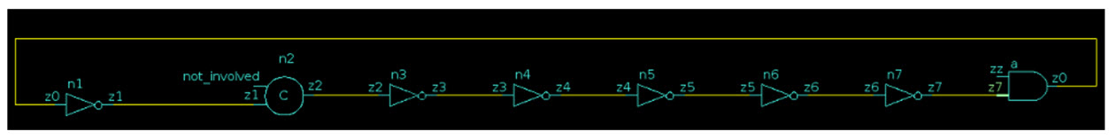
Figure 1: A zero-delay loop circuit (Mentor)
A common workaround is to add artificial delay values to the outputs of cells, in the assured knowledge that the complete SDF will have the necessary delays in place to prevent the feedback loops during the final gate-level simulation run. The addition of this delay can be achieved using the following methods:
- Manually add delays to the cell source.
- Automatically add delays to the outputs of UDPs.
- Add delays through fake SDFs.
- Do not simulate timing checks.
A complete SDF with correct timing values typically will not be available until a late stage of verification. Under such scenarios, early gate-level timing simulations using an SDF that is not timing-clean can be expensive to simulate with timing checks, if they are to be waived off or individually suppressed on an instance-basis at runtime. In this case, it is ideal to compile the netlist with the option to remove all timing checks from the design. This can help improve the performance of gate-level simulation by not simulating timing checks and printing potential violation messages that can clog a log file and/or create a performance bottleneck at runtime.
We have observed a typical performance boost of between 5% and 30% and up to 2X on various gate-level simulations by compiling a design without timing checks.
Most tools provide a run-time option to prevent the simulation of timing checks. However, we recommend compiling the design with the option to allow the simulator to apply any additional optimizations after removal of the timing check statements.
Other ways to improve gate-level simulation performance include:
- Time precision. If possible, set up simulations to run at a coarser resolution (such as ps) rather than at a finer resolution (such as fs).
- Do not log cell internals. If cell internals are logged, the simulation performance can be severely impacted (multiple-X slowdown), and the resulting debug database can end up being large and difficult to work with.
- Replace verified gate-level simulation blocks with RTL or stubs. As a full-chip configuration is built through IP and sub-system integration, it is a good idea to replace verified netlist blocks with equivalent RTL blocks or even stubs with appropriate port connectivity. Thi process can provide a significant performance boost as you verify only what is required.
- Switch timing corners during simulation. A very effective way to improve gate-level simulation throughput when simulating multiple timing corners is to switch the SDF at the start of simulation. This saves precious recompilation time in gate-level designs.
Validating ATPG and BIST tests
Because verification teams spend a considerable amount of time doing ATPG simulation, this presents another important opportunity to improve gate-level verification performance.
On large-scale designs, the simulation time to run ATPG tests can vary from a few hours to a few weeks. Duration will be based on the design size, scan-chain size, and number of patterns tested. This is true whether users are doing stuck-at-fault simulation or chain-integrity-tests, and also whether they are doing serial or parallel pattern testing. Verification time is enormous for some teams, and they are actively looking to improve or shrink the time they need for running simulation. And that’s before they even get to debugging the issues.
Fortunately, there are a few ways that throughput can be improved in this context. ATPG test regressions can often be categorized into different test configurations, where multiple tests share the same test configurations.
ATPG simulation can also be split into two phases: the test-setup phase and the pattern-simulation phase. Again, in an ATPG test regression, multiple tests share the same test-setup phase and then start the pattern-simulation phase. During the pattern-simulation phase, users often have multiple patterns in a single test that are being simulated serially. Simulating each pattern can take a few hours to a few days, based on design and/or test type.
Following a few steps using the Questa simulator’s checkpoint/restore feature, users can achieve significant improvement in throughput for ATPG simulations. Here is how that process works:
- Start by identifying tests that share the same design configuration and/or test set up phase.
- Next create a set of such tests.
- Then create multiple sets of such test-sets. For each test-set, run the simulation until the test setup phase is done and then checkpoint or save the state of the simulation.
- Now users can run multiple tests directly by restoring the state and resuming simulations. All these tests can be run in parallel to efficiently use the grid system.
A single test with multiple patterns can be split to run those patterns in parallel. Based on the number of patterns test test has, our recommendation is to create sets of at least three or four patterns to get the best throughput efficiency.
When it is time for debugging a failing pattern, the user first needs to wait for the simulation to finish to find which pattern failed and then start the debug process. Using the above flow, this wait time has already been reduced. The user begins the debug process by logging the waveforms and rerunning simulation until reaching the failing pattern.
The above methodology can also be used to improve the debug process itself. It is possible to enable waveform dumping for only the pattern-simulation phase. This saves a great deal more time and disk space by avoiding unnecessary waveform logging for the initial setup phase. The user also can start simulating the failing pattern directly. He or she does not need to rerun the whole simulation from the setup phase, which can take a very long time.
Using the methodology improvements suggested in this article, verification teams can improve their gate-level simulation flows and achieve significant reductions in debug turnaround time.
We expand on these techniques with more details, more tips, and real-world examples, including cell modeling guidelines, in a new whitepaper, Efficient Modeling Styles and Methodology for Gate-Level Design Verification. Also if you want to learn more about the Questa checkpoint-restore simulation flow itself, please see the Mentor whitepaper Boosting Regression Throughput by Reusing Setup Phase Simulation.
About the author
Rohit K. Jain is a Principal Engineer at Mentor, a Siemens company, working on QuestaSim technology. He has 18 years of experience working in the EDA industry in various engineering development roles. He is experienced in HDL simulation, parallel processing, compiler optimization, and parsing/synthesis engines. He has a Master’s degree from IIT, Kanpur, India.
