Overcoming dummy fill deck limitations for analog design
CSR used a customized approach to automated dummy fill layout for AMS to address layer density and device matching issues in standard flows aimed at digital SoCs.
In advanced node IC designs, nonfunctional geometric shapes – dummy fill structures – are added to maintain layer planarity during chemical mechanical polishing (CMP).
The automated layout flows to generate dummy fill have been primarily designed for large, digital system-on-chips (SoCs). For mixed-signal layouts, these flows sometimes cannot generate both the required layer densities, and lack enough flexibility to maintain symmetry for device matching.
However, you can get better results with an approach where fill patterns are customized. This is controlled through a design entry system that is used to drive a tool command language (Tcl) programmable engine which adds fill to a variety of analog layout styles.
The growing importance of dummy fill
For several process nodes, silicon processes have used a damascene approach to depositing metal layers. It requires CMP steps to remove excess metal and isolate tracks. This CMP polishing comprises the combination of a chemical slurry with mechanical pressure.
The rate of the erosion of metal and inter-metal dielectric during polishing varies, and this can cause surface dishing and other non-planar surface effects. These in turn can lead to poor isolation of tracks and shorting [1].
To alleviate this, foundry design rules specify the area densities of specific metal layers. When insufficient metal density is present from circuitry (devices and interconnects), non-functional dummy fill shapes are added to meet the targets [2].
From 40nm, in addition to CMP induced metal density targets, density rules for base layers have become necessary to maintain thermal uniformity during rapid thermal annealing (RTA) to reduce device variability. Therefore, the fill process has become more important and more complex.
CSR’s advanced dummy fill requirements
CSR is a global fabless company specializing in wireless connectivity, location, audio and imaging devices. It relies upon foundry partners to provide a physical verification rule deck to process the layout and generate dummy fill structures to meet density targets. CSR realized that foundry-supplied decks tend to be targeted at customers developing digital SoCs.
For digital projects, the dummy fill process is done once only at the top (full chip) level. However, where there is a large amount of analog content, it is better to insert fill structures hierarchically as analog IP is integrated into the design. This means the additional structures can be included in parasitic simulations.
One issue CSR encountered when using standard foundry fill decks was that it had little control over how the decks operated. For analog designs, this could result in insufficient density control, an inability to adapt to specific device structures (such as mirrored and matched circuitry), and a further inability to alter the dummy fill shape depending on underlying layers.
CSR observed that the decks could not meet the foundry’s own density requirements for analog. In addition, the rules did not comprehend the matching requirements for specific analog circuitry that ensure it meets performance specifications. The result was that dummy fill had to be added by hand, a time consuming process.
New tool capabilities to support advanced dummy fill
The SmartFill functionality in Mentor Graphics’ Calibre Yield Enhancer has been introduced to address the challenges posed by advanced dummy fill. New functionality provided by this and similar tools includes:
- Multi-layer stack: the ability to create fill structures that extend across multiple layers
- Minimum and maximum density control
- Density gradient control
- Fill geometrical transforms: including mirroring and rotation
- Data compression: a sizeable reduction in the size of GDSII files
- Double patterning capability: the ability to color fill structures, (divide them across two masks)
- Net aware fill: the ability to apply special rules for identified critical nets
The addtional concept of ‘cell-based fill’ has been added to Calibre Yield Enhancer to simplify pattern definition and control.
For example, cell-based fill can define a ‘fill cell’ that can subsequently be placed in arrays within a defined region (Figure 1). Fill cells allow for large-scale compression of the GDS files for large IC designs, thereby saving processing and data transfer time.
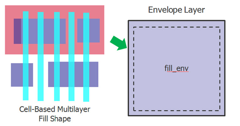
Figure 1
Cell-based fill, provided by the SmartFill functionality of Calibre, allows designers to define a fill pattern, or cell, which can be replicated over a defined region. (Source: Mentor Graphics – click image to enlarge)
Advanced dummy fill programming: a case study
To demonstrate how to deal with the complexities of advanced dummy fill for mixed-signal design, this section describes how CSR used SmartFill with Cadence Design Systems’ Virtuoso, its custom analog design platform.
The Calibre platform supports Tcl coding constructs with purpose-built Tcl Verification Format (TVF) extensions to help with physical verification. These extensions support scripting using batch commands for layout manipulation and the automation of Calibre rule file submissions.
Using the DESIGNrev component of Calibre, users can create and execute these scripts, and also call on a graphical layout view with interactive layout manipulation functions. Based on these capabilities, Calibre DESIGNrev forms the core environment from which CSR’s fill flow is driven.
The number and variety of analog IP blocks in a typical CSR project precludes the creation of a unique fill rule deck for each block. Instead, CSR has sought a way for its layout engineers to tag geometries with fill directives as they create a design. They then use these directives to automatically generate the correct fill style and parameters.
As CSR’s primary analog layout entry system, Virtuoso allows properties to be associated with layers. This mechanism can be used to pass directives to the SmartFill engine and store them for audit trail purposes.
However for complex dummy fill patterns, it is not feasible to have a user manually input directives for each fill geometry. So, CSR used Cadence’s SKILL scripting and PCell description language to create a more efficient GUI interface.
First the user draws one or more fill regions. Then he or she uses a custom GUI panel to specify various fill directives associated with the region, which are stored as layer properties. These directives are described below.
CSR exploited a capability to specify multiple regions with different dummy fill directives for each, but this did still create a number of issues. First, where regions on the same layer overlapped, CSR had no way of specifying which region should be processed first. To alleviate this CSR employed a concept of ‘nested regions’ (or Russian Dolls) to resolve the processing order. Using this approach, regions can be nested but must be non-overlapping.
Once fill regions had been created and directives assigned, CSR used the layout editor to generate a text file, the ‘region property file’. This contained the region and fill directive information. The file and the GDS were then passed to SmartFill. It processed the fill regions in order, inserting fill shapes into a working GDS database as it progressed. A flow diagram for this automation approach appears in Figure 2.
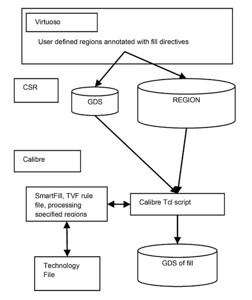
Figure 2
The flow used to insert advanced fill structures into an analog design (Source: Mentor Graphics – click image to enlarge)
Expanded dummy fill directives
Using the cell-based capabilities of SmartFill in the way described allowed each dummy fill region to be controlled in a number of ways, providing a degree of flexibility that standard fill decks lacked. These were:
- Layers: The layers to receive fill can be specified on a region basis. All settings that apply to each region are applied to these layers.
- Type: This specifies how fill is inserted within the region. Four types have been defined:
- Standard Dummy Fill: This is the conventional type of fill, including nested fill regions.
- MX or MY: This is a region where mirroring is enabled. The region is halved, fill is generated for that half, and the resultant fill pattern is mirrored.
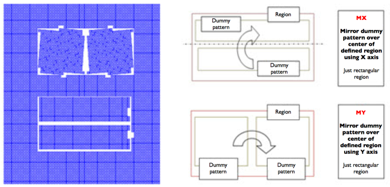
Figure 3
Standard dummy fill regions with Russian doll nesting (left). Fill mirroring around MX and MY regions (right) (Source: Mentor Graphics – click image to enlarge)
- Replicated: This is potentially the most powerful type of fill directive. Many circuits in analog layouts are replicated in arrays, and designers want the same parasitic environment for each instance in each array. A fill pattern can be defined for one instance and replicated.
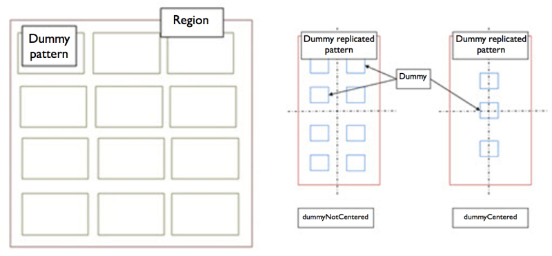
Figure 4
Fill replication (left) and centering (right) (Source: Mentor Graphics – click image to enlarge)
- Position: When filling a rectangular area, the user can choose whether to have a fill geometry at the center or not.
- Pattern: A standard foundry deck uses a staggered approach. For a tight analog layout, this approach can lead to density targets being missed. This pattern option allows users to choose between staggered and array fill patterns.
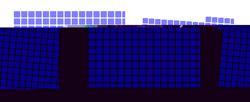
Figure 5
Arrayed fill (left) and staggered fill (right) (Source: Mentor Graphics – click image to enlarge)
- Shape: In some cases, stretched fill objects are suboptimal. This option allows users to specify the amount of stretch.
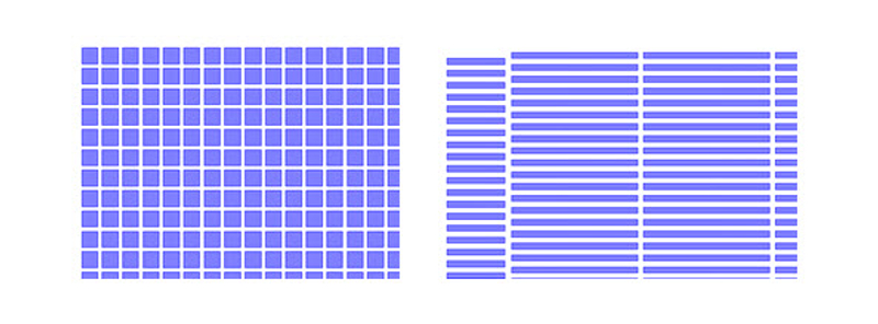
Figure 6
Square fill (left) and stretched fill (right) (Source: Mentor Graphics – click image to enlarge)
- Density: A desired density range can be specified and for adjacent (or Russian-dolled) regions, and user defined gradients can be specified. These are useful in matching densities across adjacent IP blocks.
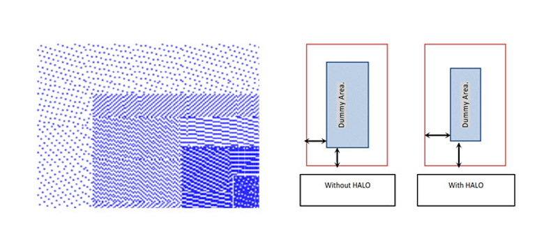
Figure 7
Russian-dolled regions of varying densities (left) and fill halo definitions (right) (Source: Mentor Graphics – click image to enlarge)
- Halo: By default, SmartFill generates DRC-clean fill patterns. However, there are cases where extra spacing is required. This can be specified as additional halo spacing.
When the property file is read, the regions are first prioritized according to the ‘order’ value within it. Then SmartFill is run via batch commands. During this process, a number of SmartFill tasks are submitted. As each job is completed, the GDS file is imported back into the original layout, so the fill generated at each stage becomes part of the database. This ensures that any new fill is placed with regard to any previously generated fill. After each placement cycle the relevant exclude layer is added to the region.
For each region, the density is calculated to meet the minimum and maximum values defined in the property file. It is measured over a defined window of 20×20 microns with a typical gradient of 5%. The target density variation between adjacent windows is <5%.
Conclusion
This approach to advanced dummy fill provides a powerful set of fill operations and a flexible way of controlling them, without requiring deck writing on a per block basis. This has many benefits for a purely analog fill flow, but the flexibility of the approach can also be used for controlling density gradients between adjacent blocks in any chip/IP integration scenario.
References
[1] “Section 1.6 Design Dependency of Chip Surface Topology”, Nano-CMOS Design for Manufacturability, Wong, Zach, Moroz et al, Wiley-Interscience, October 2008, ISBN9780470112809 59 50.
[2] “Section 5.6.5 Dummy Diffusion – Poly-Metal”, Ibid.
Acknowledgments:
The authors would like to thank their colleagues at CSR and Mentor Graphics for their contributions to the development of approach, in particular, Fady Fouad, Technical Marketing Engineer, Mentor Graphics, Bill Graupp, Technical Marketing Engineer, Mentor Graphics, and David Vigar, Senior Director of Advance Process and Development, CSR.
About the Authors
Colin Thomas is the DFM Technologist in the Advanced Process Technology Development Group at CSR in Cambridge, UK.
Ian Smith is a European Application Engineer in the Physical Verification Group at Mentor Graphics in Newbury, UK.
Contacts
CSR
Corporate Headquarters
Churchill House
Cambridge Business Park
Cowley Road
Cambridge
CB4 0WZ
UK
T: +44 (0)1223 692000
W: www.csr.com
Mentor Graphics
Corporate Office
8005 SW Boeckman Rd
Wilsonville
OR 97070
USA
T: +1 800 547 3000
W: www.mentor.com
