Using optimized design flows to meet PPA goals for SoC processor cores
How tuning a design flow can help optimize SoC processor cores for power, performance and area – and make it possible to do different optimisations for different cores on the same SoC.
The increasing complexity of system design means each processor core in an SoC must be optimized to meet the power, performance, area (PPA), yield and cost goals appropriate for the work it is doing. For example, a GPU handling arithmetic-intensive processing will have to meet different PPA goals to a DSP core executing audio applications. Achieving these goals is best done using design methodologies tailored to the specific core’s application need, and the latest tools, processes, IP blocks, standard-cell and memory libraries. A well thought-out design-management tool can make it easier to apply these tailored methodologies to each core.
A performance optimization flow
Many of the optimization techniques used to achieve the desired performance from a processor core rely on advanced features of the Synopsys Design Compiler synthesis tool and the IC Compiler implementation tool but the principles can be applied to other flows. Below are some of the key techniques that can help users optimize their core implementations more efficiently and to improve the overall core performance.
Optimizing floorplans
One of the most important steps in producing a high-performance core implementation is to work from a good floorplan. The earlier you can refine the floorplan the faster your design should converge on its PPA goals. Synopsys Design Compiler Graphical (DCG) enables users to execute early floorplan analysis and refinement. There are several techniques available for refinement including applying placement bounds early in the design flow and using dataflow analysis. This work improves correlation with the final placement generated in the later stages of the design flow. Based on work performed across a number of different processors, these are the steps we recommend users perform to generate a better floorplan sooner:
- Execute the first compile in DCG with initial bounds
- Analyze cell utilization, making any changes needed to avoid excessively high/low utilization, or other issues seen in placement
- Re-run the first compile with bound changes from the analysis above
- Analyse timing to validate prior bounds changes and look for further areas of improvement (cell hierarchy can be a useful analysis tool at this stage)
- Analyse for congestion (same process as above: validate prior changes and look for more)
Executing these five steps represents one pass through the refinement process, however it is expected that multiple passes will be required. In the example design shown below, using one of the latest processor cores, it took six passes through this process to remove all of the congestion, fill any under-utilized areas and ensure that all the critical paths are where they should be. This enabled usto reach an optimal starting floorplan which only needed minor adjustments later in the design flow.
Figure 1 Multiple rounds of floorplanning help ensure a design’s implementation has a good starting point (Source: Synopsys)
place_opt -area_recovery -spg -congestion -optimize_dft -effort high
proc_auto_weights
psynopt
proc_auto_weights –wns
psynopt
where the proc_auto_weights command is used to adjust the weighting of the path groups (TNS by default or WNS using the –wns switch).
Adjusting latency during placement
Latency adjustments that are made in DCG are carried over into the place_opt flow with appropriate float pins set to guide clock-tree synthesis (CTS). This is most often seen in memory read/write paths where significant TNS and WNS can be saved.
Concurrent clock and data optimization
The latest releases of the Synopsys ICC place and route system includes new technology such as Concurrent Clock and Data (CCD) that delivers a significant performance boost to high speed processors. Rather than take a global perspective, the design is optimized at a local level to match the performance and skew of the clock tree to the requirements of the data paths around it. CCD technology is available at both the pre-route and post-route stages and performance improvements of up to approximately 200MHz have been seen.
Layer-aware routing
The increasing variability of the resistivity and capacitance of the interconnect layers is making it important to move critical nets higher in the interconnect stack where RC delays are not as significant. This means that many clock nets are now routed in the highest metal layers available. It is also important that routing takes into account all the process’s design rules and, in addition at 20nm and below, the impact of extra restrictions such as double-patterning lithographic techniques. It is particularly important that the router delivers as close to a finished design as possible because fixing a significant number of design-rule check (DRC) violations at a late stage is likely to impact many timing paths.
Timing closure across hierarchical boundaries
The processors used in today’s SoCs are increasingly hierarchical designs, integrating multiple processor cores, cache and interface structures. These multiple levels of hierarchy can make it difficult to reach timing closure across boundaries and produce an optimal processor design. Transparent interface optimization technology can overcome these problems by considering the whole path, including the CPU top and block level, and providing an optimization solution that is compatible with the design hierarchy but is not restricted by it.
A power optimization flow
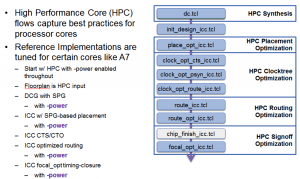
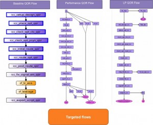
Producing a design flow targeting low power takes more than just enhancing a high-performance flow to perform power recovery. Cores that have been designed to run at low power need a separate flow. Synopsys has a tuned flow available for low-power cores that is configured to work to a target power consumption figure – the opposite of designing to a performance target and then achieving the lowest power possible as a post-processing step. The flow enables all the power-optimization options available in the individual tools and provides a convergent methodology.
Figure 2 A low-power centric HPC flow (Source: Synopsys)
Managing cell density for low power
It is important to set cell-density thresholds early on in the design process to ensure that space is available for the logic that will be introduced by additional downstream activities such as CTS and hold-time fixing.
Using library technologies to reduce power
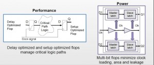
Synopsys DesignWare HPC libraries include special cells that can be used to reduce area and power, such as multi-bit flip-flops that reduce clock loading, area and leakage.
Figure 3 Merging flip-flops can save area, power and leakage (Source: Synopsys)
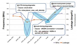
Figure 4 A generic flow may not be able to meet performance targets at the required power (Source: Synopsys)
- Timing degradation during clock-tree synthesis, causing excessive clock skew because the design is too dense to allow clock buffers to be placed in optimum locations.
- Timing degradation at routing, possibly because of differences between virtual route and detailed route, or because of additional crosstalk.
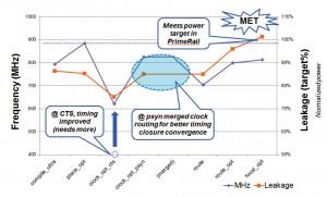
This would not be a significant problem in a performance-based flow, as in the final stages the tool can recover performance at the expense of additional power, which is what we see in Figure 4. Applying the low-power optimized flow to the same CPU design leads to a better result.
Figure 5 A power-optimized flow helps meet the required power target (Source: Synopsys)
- Timing has improved during clock-tree synthesis
- Routing issues have been solved
There is some timing recovery in the last stages of the flow but it does not cause as big an increase in power as using the previous approach and therefore the power target is still met.
An area optimization flow
The first step in optimizing for area is to ensure that the starting floorplan will meet both area and performance requirements. This means squeezing the design so that it doesn’t have any wasted space but that it is still routable. There are also switches in the tools to optimize for area. Design Compiler Graphical has switches that find improvements to reduce area without impacting timing. In one processor design, simply executing:
optimize_netlist –area
reduced the total cell area by 4%. Another significant source of area optimization is the choice of library. Synopsys has a DesignWare HPC library available (for the TSMC 28HPM process) that includes 125 extra standard cells. Using these can cut area and improve power without impacting timing. There are also new ultra-high-density and multi-port memories in the HPC design kit, which can be particularly effective when used in multicore designs.
Optimizing a multicore SoC
Each processor core within an SoC needs to be optimized for its specific power, performance and area targets. This can be done using flows that have been set up to optimize for a particular characteristic, backed up by the engineering insight to know how to prioritize the goals for each core to achieve the right balance of PPA. In practice, this means finding an easy way for designers to switch between specific, targeted, optimized flows, depending on what they are trying to achieve for a particular core, block or complete SoC.
Figure 6 Lynx Design System enables multiple optimized flows to be accessed from a single user interface and within a single runtime environment (Source: Synopsys)
Conclusion
Current SoCs integrate multiple processor cores that require individually targeted optimization for PPA. The ability to execute multiple optimized design flows under one user interface and combined with best in class tools, libraries and engineering expertise forms a compelling package that allows designs to meet their overall SoC and system PPA goals.
Authors
Jon Young, director, Synopsys Professional Services, is one of the world-wide leads for physical design within Synopsys Professional Services. Current responsibilities include defining SPS’ high-performance core (CPU and GPU) strategy and managing the difficult transition to 16nm. Previous duties have involved the establishment, development and mentoring of SoC design centers across multiple geographies in Europe, India and Asia.
Prior to Synopsys, Jonathan has held various technical and application management positions at Sony Semiconductor and Texas Instruments. In the course of his 25 year career in SoC design and implementation Jonathan has been responsible for taking over 100 designs through tape-out to silicon in technologies ranging from 3um to 28nm. Jonathan has a B.Eng (Hons) in electrical and electronic engineering from the University of Reading, UK, and is a member of the Institution of Engineering and Technology, UK.
Yukti Rao is a product marketing manager for Synopsys Professional Services. She joined Synopsys in 2009 and has extensive marketing experience with EDA tools and services. She has over 15 years of experience in semiconductor and EDA industry having held various positions in design, applications and marketing. She has a masters in electrical engineering from University of Arizona.

