Improved power management and faster time to market?
Power management is a critical element of the power, performance, and area (PPA) goals set for every integrated circuit (IC) design. Over-design the power grid and valuable area is wasted; under-design it and the IC fails to meet its designed voltage (IR) drop levels and electromigration (EM) protection requirements.
As a best practice, most design teams design the power grid to be efficient for a majority of the design, then apply layout enhancements after design implementation to optimize specific areas in the layout that must support greater power usage. The problem with that approach? Trying to apply design modifications with a place and route (P&R) or custom design tool.
P&R tools were designed to, um, place and route. That is, place logic cells and route the connections between them in digital designs. Custom design tools were designed to enable analog and mixed-signal designers to create layouts that address the specific needs of analog circuitry. What neither of those types of tools were designed to do? Provide automated, analysis-driven, signoff-quality layout optimizations.
But wait, you thought those tools had layout modification capabilities? Well, yes, but only as ‘add-on’ functionality. Using P&R or design tools to modify layouts after design implementation is typically challenging and time-consuming, and the results can be underwhelming in terms of both the quality of results and performance. And design teams may often find themselves ripping out and replacing the suggested modifications when they get to signoff because they are note compliant with the signoff design rule checks (DRC).
Let’s go back to that idea of automated, analysis-driven, signoff-quality layout optimizations. Over the last couple of years, EDA companies have begun introducing tools that aim to ‘shift left’ targeted activities in the design and implementation flow. The concept of shifting left is based on performing tasks that have traditionally part of signoff verification earlier in the flow. Finding and eliminating design issues early on can be much easier than trying to correct issues when the design is complete and open space is at a premium. The important part of the shift-left process is that these tools are designed specifically to run in various design stages, but return signoff-quality results.
For example, Siemens EDA just introduced the Calibre DesignEnhancer tool. It enables design teams to quickly and easily implement DRC-clean layout optimizations during custom design and digital IC implementation that are automated, analysis-based, and correct-by-construction. Built on the Calibre nmPlatform, the Calibre DesignEnhancer tool leverages foundry-preferred Calibre design rule decks, Calibre connectivity data, and industry-leading runtimes to improve both design team productivity and design quality.
There are currently three Calibre DesignEnhancer use models available to address specific design needs following implementation:
- Via insertion to reduce IR drop and moderate the impact of via resistance on manufacturability and reliability
- Parallel run lengths insertion to lower resistance on power grid structures
- Filler cell and DCAP cell insertion to prepare designs for physical verification
With the Calibre DesignEnhancer tool, design teams can choose to use any or all these use models, as needed, within a single standardized tool environment.
Via insertion
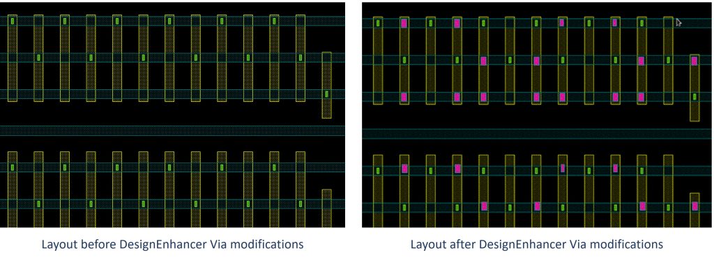
The Calibre DesignEnhancer Via use model automatically maximizes the insertion of DRC-clean vias on user-specified nets based on two drivers: insertion rate and runtime (Figure 1). Via prioritization and multiple via configurations improve the manufacturing robustness of a design. Available via operations include both multi-layer checks (such as enclosure and extension rules) and single-layer spacing and width-based count checks.

Figure 1. Automated via insertion using the Calibre DesignEnhancer Via use model maximizes the insertion of DRC-clean sign-off quality vias (Siemens EDA)
A Calibre DesignEnhancer Via kit accesses complex process node design rules within the Calibre nmPlatform, such as net type spacing, parallel run length, via count, and connectivity, to ensure DRC-clean vias are added at the highest possible insertion rate. The Calibre DesignEnhancer Via use model works with any via kits provided by the foundries for their technology processes, providing flexibility across multiple process nodes.
Parallel run lengths insertion
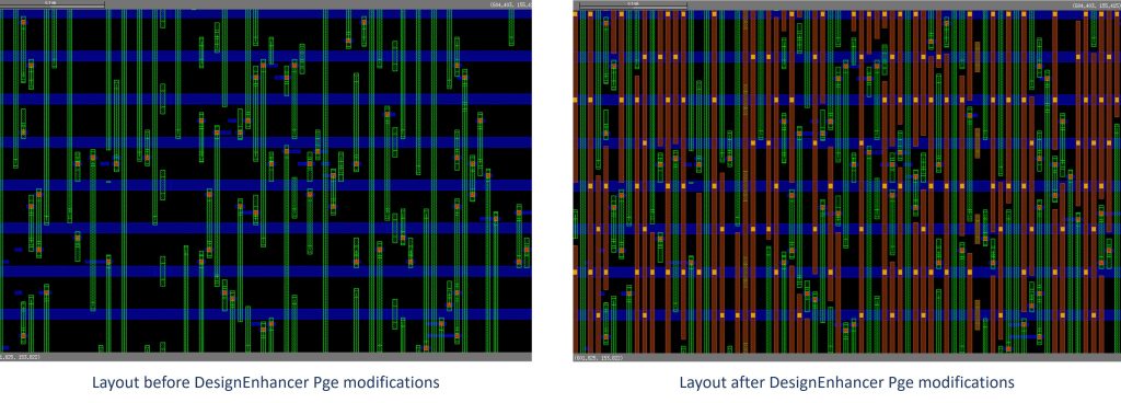
The Calibre DesignEnhancer Pge use model automatically finds open tracks and inserts DRC-clean metal and vias to create parallel runs. While the Pge use model (Figure 2) can run efficiently at the block or chip level, the best practice is to use an EMIR analysis tool to focus these layout enhancements in specific areas to achieve maximum reduction in IR drop in those areas while limiting overall impact on timing.

Figure 2. The Calibre DesignEnhancer Pge use model automatically inserts DRC-clean metal and vias in open areas to help lower resistance on power grid structures (Siemens EDA)
Filler and DCAP cell insertion
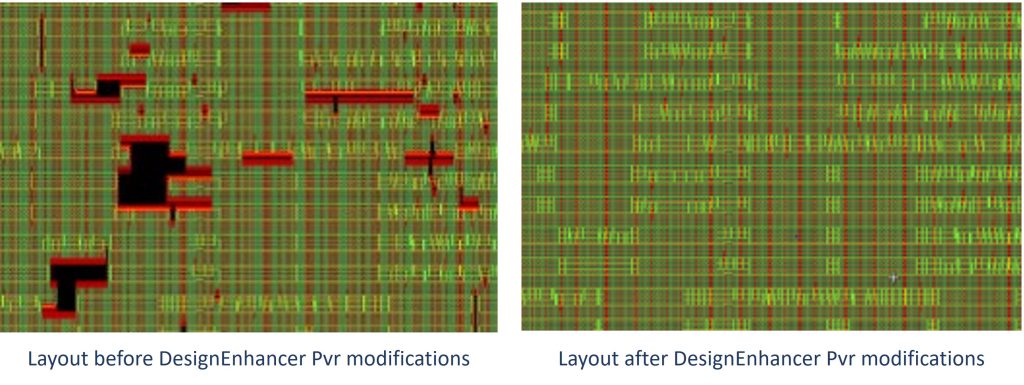
The Calibre DesignEnhancer Pvr use model replaces time-consuming and limited P&R filler cell insertion processes with push-button insertion of correct-by-construction filler cell and DCAP cell insertion in IC layouts after design implementation (Figure 3). Design teams can ensure DRC-correct layouts while significantly reducing filler cell and DCAP cell insertion runtimes. Over the span of a design flow, the Calibre DesignEnhancer Pvr use model enables design teams to begin signoff physical verification much earlier, resulting in both faster time to tapeout and higher quality.

Figure 3. The Calibre DesignEnhancer Pvr use model automatically adds filler and DCAP cells to prepare designs for physical verification (Siemens EDA)
Beyond just the idea of DRC-clean layout modifications, something else sets the Calibre DesignEnhancer tool apart from native P&R or custom design tool functionality. The Calibre DesignEnhancer tool was intentionally designed for user-friendly operation and high performance to help design teams move through these selective layout optimizations quickly and accurately.
Ease of use
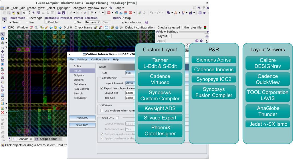
As part of the Calibre nmPlatform, the Calibre DesignEnhancer tool integrates with all major IC design and P&R tools to provide signoff-quality solutions earlier and faster in the design and verification flow (Figure 4). Push-button usability shields designers from low-level operational details and tasks, further enhancing ease of use while ensuring accuracy and speed. Calibre DesignEnhancer runtime is minimized by taking advantage of the Calibre nmPlatform ability to distribute the run across multiple machines. By leveraging the performance and quality of the Calibre nmPlatform, the Calibre DesignEnhancer tool eliminates the need for incomplete P&R processes, or costly, time-consuming custom code.

Figure 4. The Calibre DesignEnhancer tool is integrated with all leading design and P&R tools to provide a consistent interface and ease of use (Siemens EDA)
Native support for GDS and OASIS formats and the ability to directly read industry standard LEF/DEF formats ensures interoperability in all environments. Layout modifications are output to an incremental DEF file for fast, accurate back-annotation of changes to the design database to enable design teams to run power and timing analysis using their preferred signoff tools. At the same time, automated generation of the modified GDS/OASIS file allows design teams to begin signoff physical verification runs sooner.
Conclusion
As a P&R engineer or custom IC designer, you want to get your designs through implementation and on to signoff verification as quickly as possible, but you also want those designs to be as close to their PPA goals as possible. Power needs attention throughout the IC design flow to ensure a design will meet its designed performance targets after manufacturing. Performing layout optimizations such as via and parallel run length insertions during design implementation can significantly reduce IR drop and EM issues, reducing or eliminating the need for complex corrections later in the design flow, when changes are exponentially harder to make without impacting design schedules.
However, making layout modifications using built-in P&R solutions or custom code can be time-consuming and tedious. Shift left tools like the Calibre DesignEnhancer platform offer design teams the opportunity to implement selective layout optimizations to reduce IR drop and EM issues and prepare designs for physical verification in a fast, integrated environment, with the confidence that the changes will be DRC-clean during signoff verification.
To learn more about the Calibre DesignEnhancer platform and see results from real-world production designs, read this technical paper, Calibre DesignEnhancer design-stage layout modification improves power management faster and earlier.
 Jeff Wilson is a Product Management Director for DFM applications in the Calibre Design solutions organization at Siemens Digital Industries Software. Before joining Siemens, Jeff worked at Motorola and SCS. He holds a B.Sc. in design engineering from Brigham Young University and an MBA from the University of Oregon.