How automated static checks help verify complex circuits for better performance and reliability
Learn how power-intent, LDEs, ESD and voltage-aware spacing techniques can particularly benefit from the use of static verification checks.
To combat issues such as increases in off-state leakage and the growing dominance of parasitic resistance and capacitance in modern IC designs, engineers use a wide variety of techniques. These include different metals for local vs. global routing, clock and power gating, multiple clock and power domains, different circuit topologies, and so on. These techniques help them achieve the desired power and performance but also add to complexity and create new challenges for verification flows and EDA verification tools.
In particular, checks performed using manual verification techniques or by running dynamic simulations with SPICE are cumbersome, time-consuming and no longer sufficient to guarantee full coverage in many cases. New EDA methods that provide automated static check verification can help engineers ensure that not only are their designs robust against electrical failure and will perform as expected, but also that they can be delivered on time. Let’s look at a few areas where these checks can be applied with great results.
Power-intent static checks
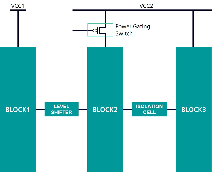
When implementing a multiple power domain IC, designers and implementation engineers commonly use special circuit elements such as voltage regulators, header and footer switches, level shifters, isolation cells, and state retention cells (Figure 1). Depending on the application and the type of circuit being used, these components provide a variety of performance benefits, such as a clean, noise-free supply to analog intellectual property (IP), the ability to gate (shut-off) power to a certain area of a chip, scaling voltages up or down independently for selected IPs, or meeting high current demands using multiple voltage regulators.

Figure 1. Verifying accurate use of elements such as level shifters, isolation cells, and power gating switches inside a low-power design requires specialized techniques (Siemens EDA – click to enlarge).
Given the typically large number of domain crossings in modern designs, manually locating every missing level shifter and isolation cell is virtually impossible if you ever want to meet your deadline. Running SPICE-like simulations to find these missing low power cells is also cumbersome, time-consuming, and resource-intensive. To catch missing low-power cells, designers must be able to isolate a particular path and correctly attribute the changes in leakage to that path. This is a non-trivial exercise for a large SoC with hundreds of inputs. Merely looking at the output values of a SPICE simulation to catch missing low-power cells is not always sufficient. Depending on the leakage and drive strengths of devices, and the depth of the downstream logic, signals that are in tristate or high-Z condition at the boundary crossing might potentially resolve in either direction as they pass through the logic chain, returning false negatives.
Designers also need to check for electrical overstress (EOS) when there is a high-voltage or IO domain device driving a thin-oxide device rated to work at much lower core logic voltage values. In this case, the use of a high to low level shifter is essential; otherwise, the low voltage or thin-oxide device is at risk of damage due to oxide or source-drain junction diodes breakdown caused by EOS.
Automated EDA static check verification tools that run at the transistor level can identify structural issues and locate missing low-power cells, missing bulk and well connections, and yet more. They can provide full coverage with minimum manual intervention, offering a significant advantage over a dynamic simulation that requires not only testbench setup and validation, but is also expensive and time-consuming to run.
ESD verification
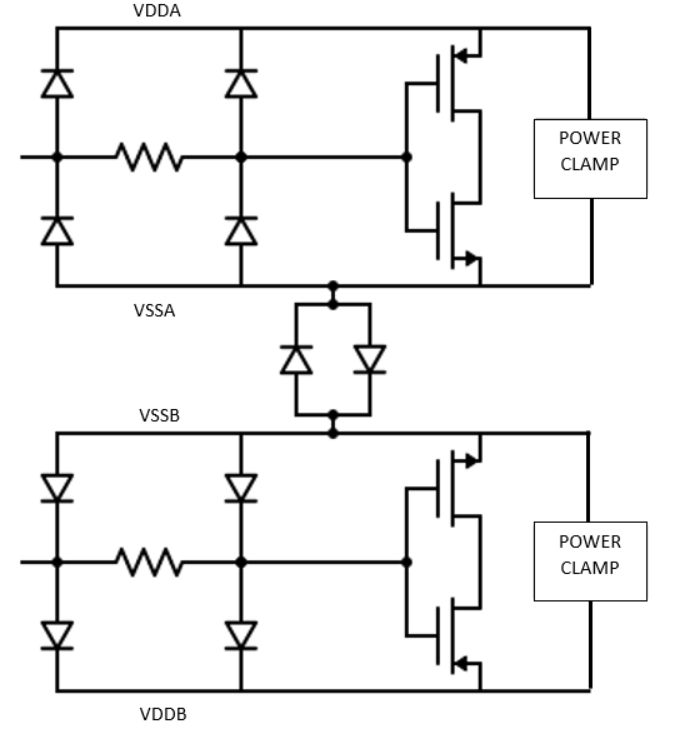
Various protection structures are used inside ICs to avoid damage from electrostatic discharge (ESD) events (Figure 2). These structures shunt the high ESD current away from the functional or core circuit, protecting them from damage.
Ideally, these ESD protection elements act like an open circuit during the normal or functional mode of operation, but during an ESD event, they turn on, providing a very low resistance path through which the ESD current discharges. Traditional ESD protection verification approaches that use parasitic extraction followed by SPICE simulation on these circuit blocks have major limitations in their ability to handle large designs and provide reliable simulation results in a practical run time. Full-chip simulations for large SoC designs are essentially impossible to run in any realistic timeframe. On the other hand, just running simulations at the IP and block level is no longer sufficient, since they fail to capture the effect of parasitics introduced during the integration of these blocks at the higher level.
Modern designs contain large power domains and there is a significant parasitic resistance contribution from the power-ground network. So, the ESD protection elements are now distributed at multiple locations inside a chip. To achieve reasonable runtimes for running dynamic ESD simulation, designers must manually create schematics that retain only the relevant blocks, removing all the blocks that do not contribute to the simulation. Manual processes are inherently error-prone, and there is always the risk of accidentally excluding necessary IP from the schematic. Using assumptions for interconnect resistances, and manual calculations, extrapolations, or approximations of path resistances, is not only insufficient, but also highly risky.
Automated static electrical rule checks (ERC) can traverse through a design and accurately identify all the topologies for ESD protection elements in a comprehensive and reliable manner, minimizing the chances of human error. Using a static check tool, designers can check the resistances of the different discharge paths and compare them against technology constraints much faster than they can run a dynamic solution, and they can run the check at the full-chip level in a practical runtime.
Designers must also ensure that interconnects are properly sized and that there are enough vias to handle the large current during the ESD event. Failure to meet these limits can cause a degradation in the resistance of wires or vias, or even open and short circuits due to burning and melting of the wires. Static check tools can run electromigration and current density (CD) checks at the full-chip level to ensure that every wire segment and via carries current that is less than its threshold or limit value set by the foundry, to avoid any capacity issues encountered when running a dynamic simulation.
Voltage-aware spacing checks
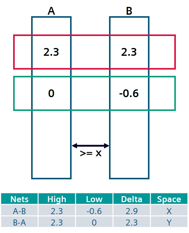
For advanced nodes and designs with multiple power domains, the required spacing between interconnects is dependent on the voltages on the interconnects (Figure 3). The wires must be adequately spaced to mitigate the effect of time-dependent dielectric breakdown (TDDB). This spacing is critical, particularly in high-reliability applications for end-markets such as automotive, biomedical, and datacenter.
Running dynamic simulations to obtain voltage on every interconnect segment in the design and annotating these voltages on the layout to run DRC is an almost impossible task for today’s large designs. Manually adding marker layers to the layout to perform DRC between nets in different domains is – you guessed it – a time-consuming and error-prone process. Because designers must rely on input vectors when adding markers, any incomplete set of input vectors makes it very challenging to obtain full coverage and prevent false violations.
Using an EDA tool that can perform static voltage propagation and topology-aware checks, designers can check for different spacing constraints inside their layout, taking into account the different delta voltage ranges, as shown in Figure 3. To fully automate the process and eliminate the need for manual marker layers, the tool must also be able to annotate the static voltage propagation simulation results to the physical polygons inside the layout.
There is some chance that the results will contain unintended pessimism – particularly for special circuit topologies such as low-power cells – due to the static voltage propagation scheme. To minimize this effect, designers can provide input constraints to the tool, or override the default values by supplying values obtained by running a standalone dynamic simulation as input to the static simulation algorithm.
Analog layout-dependent checks
You must analyze layout-dependent effects to avoid reliability and performance issues. While some can be caught during post-layout simulation, others will not be seen until the design is on silicon, so finding and eliminating them during design verification is essential to success [1].
Radio frequency (RF) and analog mask layout designers typically follow various layout precautions that minimize the effects of crosstalk, mismatches, noise, etc. [2]. Some common techniques used by these designers include device symmetry, current orientation matching, dummy device insertions, common centroid and pitch between devices, and electrical parameters matching [1].
For example, differential circuits are commonly used in RF and analog designs for amplifiers, mixers, charge pumps etc. (Figure 4). In a fully differential circuit, any lack of symmetry between devices affects their ability to suppress the input common mode noise, introduces input referred offsets, and causes finite even order distortion [2]. These impacts make it critical to check for potential asymmetry in these circuits before tape-out.
Designers must ensure that all the best layout practices are followed for these designs. Just using visual inspections or layout reviews to verify these requirements are followed is not ideal, as it is possible they will miss violations that can prove costly. Also, due to the size and complexity of today’s designs, it is difficult to obtain sufficient coverage in many cases.Running post-layout simulations on analog designs, while essential, can fail to catch subtle issues if the divergence from expected results is small for the given simulation conditions. Also, the device simulation models that are used for these simulations need to capture all the effects arising due to these layout-dependent effects.
A static constraint-based platform that provides automated detection of the most subtle errors in a layout implementation – such as device asymmetry and mismatches, missing dummy devices, or inaccuracy in a common centroid layout – must be run to deterministically catch these violations.
Summary
As IC designers face an increasing number of verification challenges due to technology scaling, growing complexity in designs, and challenging performance and power targets, relying on manual techniques and traditional simulation-based approaches is no longer sufficient to ensure layouts accurately implement the designed circuitry, achieve the desired power and performance, and protect against both immediate and long-term potential failure occurrences.
Leveraging powerful static checks as part of the flow early on in the design and verification cycle helps ensure designers to catch subtle errors in a quick and reliable manner. This allows them to meet the design objectives and tape out products on time. An automated verification solution that is easy to set up, provides a quick turnaround time, and can reliably verify that the design meets both technology and user constraints is vital to ensuring that design companies can deliver reliable products on schedule.
To learn more, download our whitepaper, “Improve circuit performance and reliability with automated static check verification”.
References
[1] Hossam Sarhan and Alexandre Arriordaz, “Automated Constraint Checks Enhance Analog Designs Reliability,” Siemens Digital Industries Software. Oct. 2018.
[2] Razavi, Design of Analog CMOS Integrated Circuits. New York: McGraw-Hill, 2001.
[3] Natekar, V. Vasudevan, A. Viswanath, “A 5.2GHz RF Front-End,” University of Michigan, EECS 522 Final Project, 2011. https://www.eecs.umich.edu/courses/eecs522/w11/project/group8report.pdf
About the author
Neel Natekar is a senior product engineer in the Design to Silicon division of Siemens Digital Industries Software. He collaborates with R&D, field staff, and customers to define and implement new tools and functionalities that improve and expand automated design verification and optimization flows. Prior to joining Mentor, Neel worked as a design engineer at Qualcomm, focusing on power delivery solutions for their custom CPUs. He received a B.Eng. in Electronics and Telecommunications from the University of Mumbai, and an M.S. in Electrical Engineering, Circuits and Microsystems from the University of Michigan.


![Figure 4.A fully differential mixer (University of Michigan [3]).](https://www.techdesignforums.com/practice/files/2021/05/Fig4_mixer.jpg)


