Building confidence and flexibility in 3D-IC system level design
3D-IC presents major connectivity challenges in maintaining a golden netlist and managing necessary exceptions. Learn how to manage them.
3D integration is becoming a valuable alternative to the ongoing yet challenging transistor scaling known as Moore’s Law. This is especially true for semiconductor products that are becoming limited by single die designs (e.g., in terms of form factor, size, and technology node).
Homogeneous 2.5D-IC approaches have provided an acceptable yield and are currently helping bring about the era of so-called chiplets—with its great emphasis on IP reuse. Additionally, heterogeneous integration provides even greater value since different process nodes can be mixed in the same semiconductor product.
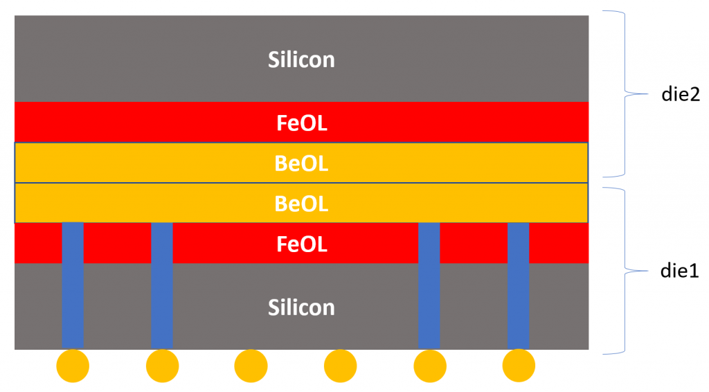
Unlike placing dies side-by-side in the 2.5D-IC approach, 3D-IC allows the stacking of different dies vertically. This reduces undesired delays as the interconnects are shorter. True 3D stacking improves the form factor even more than possible with 2.5D-IC and fan out wafer level packaging (FO-WLP). Examples of both 2.5D-IC and 3D-IC integration are shown in Figures 1 and 2.
In terms of EDA physical verification, designers need to confirm that the 3D-IC assembly is connected as expected, compared to the ‘golden’ design intent (captured as a system-level netlist). For the system-level netlist to be considered golden, the designer must be confident enough that it is the absolute reference of system connectivity.
Transitioning to advanced system-level connectivity flows
In the case of 2.5D-IC systems, designers usually build silicon interposers using the same approaches used to build digital SoCs (using traditional, automatic place-and-route EDA tools), which means that the interposer connectivity is usually captured in a Verilog netlist format. As far as the designer can tell, this is the best system-level golden connectivity reference that he or she can generate using the traditional IC flows.
But now, when graduating to 3D-IC system-level design tools and approaches, how can designers know they built the connectivity correctly?
They will need to employ equivalence checking, with which they can compare the output of the traditional connectivity capture approach (usually a single domain: CDL, Verilog, or CSV) versus the output of a new, system-level connectivity capture approach (multi-domain). In other words, you need a quick, automated, and flexible netlist- versus-netlist comparison. Once the comparison results are clean, the designer will have more confidence in using the newly introduced connectivity capture flow.
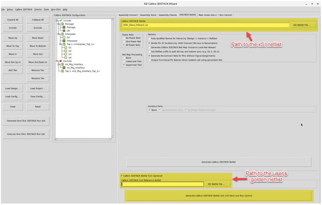
To help designers make this transition, Siemens has developed an automated approach—using Siemens’s Xpedition Substrate Integrator (xS)—in which the designer can compare with his or her traditional flow netlist (SPICE, Verilog, or CSV) versus the system-level assembly netlist generated from xSI (CSV). This automated netlist-versus-netlist comparison is performed using Calibre tools accessed through an add-on feature integrated with xSI. Figure 3 shows the interactive GUI (wizard) that is used for the netlist-versus-netlist comparison.
Users can see whether the xSI system-level connectivity matches their traditional flow connectivity by generating the netlist-versus-netlist runset out of xSI, executing the comparison, and viewing the generated comparison report. If the report is clean, xSI correctly built the system connectivity as intended.
System connectivity exceptions in 3D-IC multi-substrate assemblies
In some cases, a system source netlist is not enough for LVS verification of 3D-IC multiple substrate systems. In these cases, designers need to ‘short’ some signals together in the substrate layout. These shorts create a mismatch between the layout and the source netlist. Although these differences are reported in the LVS comparison results, they are intended by the user (usually temporarily).
For the user to differentiate between the intended LVS issues and the real LVS issues, the intended LVS issues need to be somehow waived from the LVS results. One obvious solution is to modify the system source netlist to match the physical layout implementation. However, this is not desirable since the system source netlist needs to be golden and frozen across different physical implementations and iterations.
Thus, designers need a quick, automated, and flexible way to handle connectivity exceptions in a 3D-IC design that enables them to waive intended shorts in the LVS comparison results. Siemens’s Calibre 3DSTACK supports a ‘net mapping’ feature that can be utilized to account for the intended shorts. The shorts list can be considered a net map file, and it can be automatically included in the Calibre runset using a wizard that is integrated with xSI.
Another challenge can arise when an assembly includes both an interposer and a package substrate for the same connection; the IC design team (building the silicon interposer) may use a different net naming methodology than the packaging team (building the organic substrate). The system-level designer then ends up in a situation where the same port name can be assigned to two different net names. For example, the same die-to-BGA connection can be assigned to two different net names: C4_PKG (packaging team naming) and C4_INT (interposer team naming).
xSI can recognize a connection across substrates, even when two different net names are assigned to the connection. This is achieved by applying the xSI interface part feature.
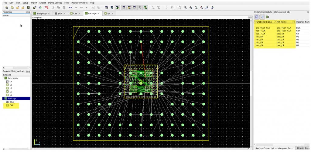
The interface part function is used to connect two different substrates in xSI (called floorplans or designs). An example of an interface part is highlighted (on the left) in Figure 4.
As seen in Figure 4, there are two substrates: ‘Interposer’ and ‘Package’. For the ‘TEST_CLK’ signal, there are two different net names: ‘TEST_CLK’ in the interposer domain and ‘pkg_TEST_CLK’ in the package domain. Although the net names are different, the ‘TEST_CLK’ signal is correctly tracked across the system due to the existence of the “C4P” part (the interface part).
Conclusion
For 3D-IC assemblies, the designer must ensure that the system-level netlist is golden. This can be a challenge in the case of a newly introduced design flow. Xpedition Substrate Integrator (xSI) and Calibre 3DSTACK offer a fast, automated, and flexible netlist-versus-netlist approach so users can be confident that they built the system-level connectivity correctly.
Another challenge in the 3D-IC design flow are connectivity exceptions, in which different design versions can include intended shorts that need to be waived for more user-friendly, system-level LVS debugging. xSI and Calibre 3DSTACK allow the support of known shorts and the tracking of connectivity between the IC design and package design domains.
To gain greater insight into the challenges of 3D-IC connectivity and the Siemens xSI and Calibre 3DSTACK solutions, please read the full paper Making the right connections: Managing the system level netlist and its exceptions in 3D-ICs.
About the author
Tarek Ramadan is a senior 3D-IC application engineer in the technical solutions sales (TSS) organization at Siemens EDA, Siemens Digital Industries Software (DISW). He drives EDA solutions for 2.5D-IC, 3D-IC, and wafer level packaging applications. Prior to that, Tarek was a technical product manager in the Calibre design solutions organization at Siemens EDA. Ramadan holds BS and MS degrees in electrical engineering from Ain Shams University, Cairo, Egypt


