Power grid analysis for 2.5D and 3D IC systems
PGA has been IC-centric for mainstream 2D configurations. It must become system-centric for 2.5D and 3D systems.
Interposer-based 2.5D and stacked 3D IC integration are high profile ‘more than Moore’ strategies now enabling the incorporation of additional capabilities within ever-smaller form factors. A major design challenge for both is power grid analysis (PGA). Existing software is well-defined for use on planar designs, but needs to be extended and enhanced for 2.5D and 3D to fulfill new requirements and use models. Let’s look at the key changes that will be necessary.
System-centric power grid analysis
Power grid analysis has been an IC-centric process for mainstream 2D configurations. It must become system-centric for 2.5D and 3D systems.
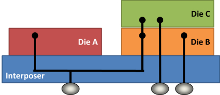
For example, as Figure 1 shows, several die in any 2.5D or 3D IC system will typically share the same network supplies. The incoming generation of PGA solutions must concurrently analyze these die, as the voltage drop for one could be directly linked to another. Also, PGA solutions must support various 2.5D/3D die configurations – addressing, for example, placement, orientation, and stacking order – as well as models for inter-die interconnects.
Figure 1 Shared power supplies between dies A, B, and C
Heterogeneous nodes
The presence of multiple die also highlights the need for 2.5D/3D PGA solutions to support heterogeneous technology nodes. Each die in a system may have be designed on a different process, as dictated by node maturity for the applications it contains. So, a system could contain die designed at 40nm and 28nm, and an interposer designed at 65nm.
Enabling incremental technology file definition and calibration is also a plus. End users then need only calibrate the new part of a stack definition related to the 2.5D/3D integration, rather than re-calibrate the IC portion of a stack definition.
2.5D and 3D integration ‘objects’
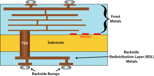
Then there is the question of how everything within a system is mounted and connected. Figure 2 shows how 2.5D/3D flows must take account of the specific ‘objects’ required for vertical integration. These can include backside bumps and backside metal layers.
The latter is a good illustration of the type of challenge these present for PGA software: The backside metal layers in a 3D structure are routed at 45 degree angles instead of the usual 90 degrees used for front-side metal layers.
For 3D, there is then the further need to support the use of through-silicon vias (TSVs) between front and backside metals. Meanwhile for 2.5D systems, PGA tools must be able to handle passive interposers that contain only metal (no devices underneath).
Figure 2 2.5D/3D-specific 'objects'
Use models
Due to the typical size of 2.5D and 3D systems, and the additional complexity introduced by the possible need to integrate third-party die, PGA solutions must be capable of running in three different modes.
1. Power model-based power grid analysis
Power model-based PGA is already implemented in existing solutions. Each of the die is represented by its compact power model, and the PGA software analyzes the full 2.5D/3D IC system using those models and their connections. This mode can be run fairly quickly to provide a high-level PGA of the system, though the only issues that it detects are related to inter-die connections.
Only one additional degree of complexity must be considered when running a power model-based PGA on a system incorporating multiple technology nodes. Power models are generated for technology node-specific corners, so PGA solutions here must be able to handle multi-die systems represented by compact power models generated for different corners. For instance, one 90nm die model is generated for a 1.2V corner, while a 65nm die model is generated for a 1.0V corner.
2. Full 2.5D/3D power grid analysis
This mode is not covered by existing PGA solutions and is also computationally expensive.
End users want to analyze the voltage drop on specific multi-die nets similar to those shown in Figure 1. However, to provide such visibility, the software’s capacity and turnaround time must be several orders of magnitude greater than seen in PGA solutions already on the market.
3. Hybrid power grid analysis
The hybrid solution is induced by 2.5D/3D third-party die integration. It can handle a mix of compact power models and dies (Figure 3). In a given system, a third-party die is only represented by its compact model for integration into the system PGA.
Figure 3 2.5D or 3D PGA using a third-party die power model
Power grid analysis within the design flow
To detect power grid issues early and then efficiently diagnose and correct them, 2.5D/3D PGA must be run at different stages within the design flow. Beyond signoff PGA, further analysis is required during implementation at the floor planning, post-CTS, and post-route stages. At each, the effect of the system on a given die must be taken into account to find power grid issues as early as possible.
2.5D/3D PGA systems should allow users to analyze all dies in the system easily. This can be achieved by offering multi-frame capability or die-to-die browsing in a given stack. Such capabilities allow the user to review, diagnose, and debug power grid issues efficiently. Die-to-die browsing should be fairly straightforward to implement, assuming that the solution can handle the typical data size without freezing. An efficient multi-frame capability will be more of a challenge, but such a feature will be particularly useful to users trying to debug a dynamic PGA run.
Power grid analysis output
Any 2.5D/3D PGA solution must be able to generate a complete or a partial power model of the full system that can be used for packaging/board power integrity analysis. This partial model generation is particularly important because of the likelihood of third-party integration.
For instance, if a supplier is analyzing a die on an interposer that will be connected to another die by customers, the supplier will need to deliver both a power model for the first die and the parasitics netlist for the interposer. Customers need all this information to run analyses encapsulating the power model, the interposer parasitics, and their own die, to have a comprehensive PGA of the final system.
Conclusion
Power grid analysis for 2.5D/3D ICs requires capabilities well beyond those in the simple power model-based analysis tools currently available. Power is one of the biggest challenges in 2.5D/3D IC implementations and issues that arise here cannot be solved solely at the RTL level.
To enable the semiconductor industry to fully embrace 3D integrations beyond just 2.5D, memory stack, and wide IO applications, Power grid analysis solutions must begin to address the requirements discussed here, especially if the goal is to have a true homogeneous 3D IC integration flow with multi-die, robust power grid floor planning capability.
About the author
Christen Decoin is Product Marketing Manager for New & Emerging Markets for Calibre Design Solutions at Mentor Graphics, responsible for driving early-stage new market analysis, product definition, and product launch.
Christen was previously responsible for Mentor’s participation in the DeCADE Nano2013 program focusing on parasitic inductance, 3D IC, and high frequency extraction. Before joining Mentor Graphics, Christen was the director of application engineering at Sagantec and senior product marketing manager for DFM, OPC, and OPC verification at Brion Technologies.
Contact
Mentor Graphics
Corporate Office
8005 SW Boeckman Rd
Wilsonville
OR 97070
USA
T: +1 800 547 3000
W: www.mentor.com


The 2,5D and 3D designs pose power requirements beyond the IR-drop over the interfaces created. TVS, interposers, etc. have to be able to handle, in the worst case, short circuit currents in particular when the 3D die on top is free to choose e.g. memory. As long as the footprint stems is an insufficient requirement and the full power cycle from the ‘host’ has to be known upfront and/or specified my maximum load requirements.