Straighten up and fly right
January 20th marked the 40th anniversary of the F-16’s maiden flight. The Fighting Falcon was the first military production fly-by-wire jet.
It cleared the way for undreamt-of maneuverability thanks to a design that incorporated an inherently unstable wing surface. There was just one problem, a pilot could not fly it in the traditional sense. Rather, software monitors the minutiae of the wing airfoil and makes numerous instantaneous small checks and adjustments. The pilot flies by intent instead of direct and complete control.
Figure 1 The original F16 prototypes in flight (Source: USAF)
Managed complexity beyond human but within computational control took the jet fighter into a new age. The F-16’s designers did such a good job that updated versions are still being manufactured today. Meanwhile, the advantages of fly-by-wire have moved over to even our cars, notably in the form of anti-lock brakes.
In PCB design, we are used to the idea of software automating tasks that were previously performed manually – or with considerable manual design input. But a comparison with the F-16 highlights another aspect of automation: How do you address technical innovations that require huge computational help from Day One?
Three PCB-related innovations pose this question today:
- Advanced packaging
- Embedded actives
- High density interconnect
The pressure on designers to deliver ever thinner, ever faster and ever more power efficient products means they have to adopt these techniques. They must also do so according to tight cost budgets and deadlines.
But from the get-go each technique brings with it huge complexity crossing multiple disciplines in a design-and-fabrication flow, complexity that is far beyond solely human control.
Advanced packaging
3D-IC leverages through-silicon-via (TSV) technology so that multiple chip die can be packaged together and connected to each other through a silicon interposer. This lowers cost, raises interconnect and inter-die performance, improves yields due to defect densities, and opens up scaling opportunities at the package level. The packaging process also becomes more robust for high volume manufacturing.
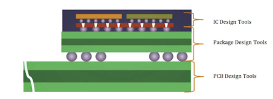
The trend toward 3D-IC shifts ‘chip’ design from monolithic silicon to a package of chips assembled in one product. Think about that. ICs have been a sub-system with the IC on a substrate, which is a PCB of its own. As the stack grows vertically, the design of each layer slowly shifts from traditional IC design to package design to PCB design. As interposers make that process gather pace, the end result must embrace three design disciplines that have not historically interacted and whose knowledge of each other’s ‘black arts’ varies greatly.
Figure 2 Different design disciplines are converging for 3D-IC (Source: Mentor Graphics)
Embedded actives
Embedded actives offer many of the same advantages as 3D-IC/interposer technology. Because embedded actives are buried in the PCB, the benefits of lower mounting inductance are much higher and the height cost goes to zero.
But the packaging design complexity shifts to the fabrication process. Much tighter cooperation is needed between design, fabrication/assembly, and test. Boundaries blur as you turn your intent into a final product. Chip and PCB sub-unit design are no longer discrete steps to be carved out, done in isolation, tested separately and merged at the end. They must be grouped together and done in combination.
Figure 3 IC in laminate, face up, with laser vias metal filled (Source: Mentor Graphics)
High density interconnect
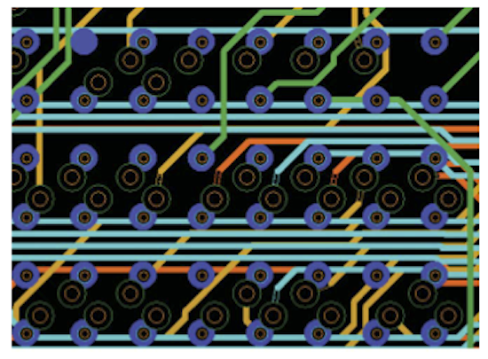
The attractions of high density interconnects are numerous and varied. For example, HDI allows us to achieve much more rewarding fan-out and escape on a large BGA, leaving open routing channels on inner layers. The smaller vias allow for more interesting and productive fan-out patterns treating each region of the package uniquely, addressing the different routing needs as you get farther from the chip’s outer edge.
However all these new HDI options throw up a dizzy array of possibilities. How can any individual intuitively know which is optimal?
Figure 4 Wide routing channels as a result of HDI fanout (Source: Mentor Graphics)
No more divide and conquer
Given the broad design options offered by these techniques and their interdisciplinary nature, we must differentiate between insightful design and repetitive calculation. The designer should provide the inspiration and direction. But once the design’s specifics become numbers, maintaining intent should be delegated to software.
Some designers cordon off sections of the 3D stack and intuitively add design assumptions, such as die or package pin-outs. They then design the ‘manageable’ sections as independent unit. It is a classic ‘divide and conquer’ strategy.
But it cuts the benefits of 3D design. It adds false limits. Partitioning the problem severely constrains the range of possible solutions and thus diminishes the advantages.
HDI as an example
A high-density fanout illustrates the impractical nature of divide-and-conquer. The package is designed assuming the PCB does not matter. The PCB is designed assuming the package is a black box. To achieve the optimal any-angle BGA fan-out with HDI routing, a cordoned-off strategy starts by taking a stab at a ‘good’ initial design feature, such as a via size. It then makes more ‘good’ stabs at the fan-out angle, layer routing bias, and NSWE break-out.
These become fixed assumptions before the fanout and escape are attempted. The resulting escaped BGA almost certainly will not be optimal. A whole range of options and possibilities has been ruled out – not arbitrarily, but still by ‘guesses’.
Indeed, later in many divide-and-conquer designs it becomes apparent that some of the initial assumptions should have been different. By then, performing multiple iterations for the fanout and escape of a large, mostly routed BGA package is not feasible in a traditional physical design flow.
The design intent is known, but the details take too long to accommodate and implement. The iterations are too complex. They cross too many disciplinary boundaries. At the human level, they are unmanageable.
Higher-level constraints
PCB and IC designers have long trusted software to handle constraint-driven implementations of small domains. Today’s USB and PCIe speeds require designers to set trace behavior with specific differential routing and consistent characteristic impedance. The designer enters these as rules, not trace shapes. Then the layout software ensures the rules are always followed. A little more intent is provided by a PCB designer sketching a route path with his mouse, then the software takes over again.
Let’s take the next step. It is time to extend constraints-driven PCB software control across the entire design.
Trying to unravel a 3D rats nest of thousands of connections by manually performing a gate or pin swap is absurdly complicated, but only with regard to the problem’s iterative experimental or mathematical aspects. If we can use a software search algorithm that optimizes a tangle of connections from die to interposer to package to board destination, it is just a computational problem.
Which, of course, is like flying an F-16. The pilot is in control but delegates a systemic task – maintaining the aerial integrity of the aircraft – to the software. In return, he gets extraordinary maneuverability, he sets the plane on its optimal path. And those pilots have now long trusted that model under far greater pressure than just about any PCB or IC designer will ever know. It’s worth taking a leaf from their flight manual.
 Randall Myers is an Xpedition Flow technical marketing engineer at Mentor Graphics


