Putting it all together to accelerate 3D IC design
Learn how connectivity management solutions help you manage the multiple formats in which 3D IC components are delivered.
There has been much growth and development in advanced heterogeneous packaging in recent years. They have added a high degree of complexity to 3D IC designs. As a result, managing the connectivity in these designs is even more challenging due to several factors. These include:
- The explosion of AI and high-performance compute silicon interposer designs with two, four, even eight high-bandwidth memories.
- The emergence of fanout wafer level packaging and embedded or elevated bridge technology.
- The growth in system-in-package designs with hundreds, sometimes thousands of components.

Figure 1. 3D IC components come in a variety of formats and technologies that must be put together correctly and efficiently
The novelty and complexity of this connectivity management problem introduce a great deal of anxiety and uncertainty, making them a focal point for many engineering teams.
3D IC design teams need to plan for:
- Data sharing between design teams (silicon, interposer, package, board)
- Data sharing between formats (ODB++ is the key)
- Tools to be used
- Deciding who does what
Let’s look at what you need to make the right connections in these groundbreaking 3D IC designs.
Fitting multiple formats and tools together
A key challenge facing 2.5D or 3D IC interposer-based designs is the disparate format of the data sources. With the emergence of chiplet solutions, this problem is becoming even more of an issue as data from multiple sources is unlikely to be available in a single common format.
For example, a chiplet provider will deliver a GDS representation of the chiplet along with an Excel ball map. The silicon design is written in Verilog. The physical device uses a mixture of LEF/DEF, GDS, and CSV files. And the BGA package comes in ODB++.
The ability to use this range of data in the native formats is a critical part of the design process, especially in the early stages. So, a planning tool that manages all this disparate data, as is, not only makes the design team’s life much easier – it is essential. Substrate design teams need a solution that can quickly and accurately aggregate many data formats into a single cohesive system representation and netlist. In other words, they need a connectivity management solution that can consume data from the various sources and formats and present it to them intelligently.
By leveraging a ‘golden’ netlist of the system, a connectivity management tool ensures that the various parts of the system stay in sync and provides a platform to validate the implementation against the netlist from a full-system perspective – utilizing a system-level layout versus schematic (LVS) verification workflow.
Just as with the variety of design data sources, the tools used by the various disciplines involved in 3D IC design each have their own formats.
For planning purposes, the interconnects between the various devices are important. This includes the physical representation of the various chiplets or dies involved, along with the platform these devices will sit on. There are tools for each of these disciplines, and each has its own format.
By supporting different tools, a connectivity management solution enables substrate teams to use the implementation solution appropriate to their target technology. The Siemens solution is not a Siemens-only flow, it works well with place-and-route tools and packaging tools from some competitors. These solutions can all work together in a comprehensive planning environment.

Figure 2. By bringing all the pieces in the 3D IC flow together, the Siemens solution enables early analysis, collaboration, and trade-offs
Substrate and interposer layout and verification
Substrate and interposer layout can involve many assembly and integration technologies and processes. So, the design tools need to be comprehensive and flexible to efficiently design modules and system-in-packages, and package-on-packages, as well as RDL-based fan-out wafer level packaging (FOWLP) and 2.5D/3D assemblies using silicon or organic interposers.
One important factor is designer productivity and design tool performance on very large designs, as it is common today in the areas of high-performance compute and AI to have designs that exceed 1,000,000 total pins, and such design should not adversely impact productivity. Many of today’s substrate technologies demand precise creation of vias, via arrays, and metal areas such that substrate production yield is maximized. Of course, substrate yield is not the only concern: Designs must electrically perform to requirements, and that requires precise rules and constraint-driven wire routing. Almost all advanced packages contain interfaces with explicit relationships and rules between the different members of an interface.
The substrate/interposer layout tool needs to comprehend and manage these interfaces. This allows the designer to focus on path planning and detailed implementation at the interface level, not just on the individual members of an interface. Many OSATs and foundries provide assembly design kits for their latest packaging technologies. It is important that design tools can consume the rules, constraints, and models contained in an assembly design kit without manual intervention or editing of any data.
Another aspect of the 3D IC design flow is physical verification. It is important to distinguish the difference between physical verification of individual components and physical verification of the total solution.
Comprehensive verification of the entire assembly encompasses:
- The die
- The interposer
- The package
- The PCB
Even when you have verified the interposer by itself or the package by itself, and you assume that the silicone team performed design rule checks and LVS at the die level, you must verify that all these pieces work correctly when put together. Teams need to do comprehensive verification of the entire assembly, in which they put all the pieces together in a single environment, then verify that all the pieces line up.
By bringing all these pieces together, the Siemens solution enables early analysis, collaboration, and trade-offs employing STCO. Putting together a design plan early also facilitates early analysis whether it is thermal, power, ball planning, routing feasibility, or any number of design tasks.
Doing this from a planning tool, and the integrations that such a tool offers, makes it easier for design teams to make intelligent decisions early in the design cycle.
And as the design matures, the questions about correctness can be answered as part of the design cycle – not waiting until the end when designers must grapple with fixed data and when issues are more costly to fix.
Shifting left 3D IC assembly verification
By maintaining the digital thread, engineering teams can use their package netlist and dies to verify that the entire system is correct.

Figure 3. The digital twin drives all downstream design, analysis, test, and substrate and assembly verification
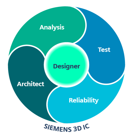
Designers can leverage the digital twin that is created by the Siemens prototyping and planning cockpit to drive assembly verification. By maintaining the digital thread made possible by the Siemens solution, engineering teams can use their package netlist and dies to verify the system is correct. The same digital twin used for multi-die, multi-substrate verification can also be used to verify a single die or substrate. This is especially useful early in the design cycle because it does not require having the complete package implemented to get value out of verification.
For many of us, any major shift in technology can be overwhelming, bringing new terminology, new design techniques, and new design processes and flows. The good news is that this can all be overcome without having to learn silicon place-and-route design tools.
The IC packaging design tool set has matured to the point where it can address not only classic plastic, organic, and ceramic packaging substrates but can also address silicon substrates driven by interposer and chiplet designs. In most cases, system and packaging teams do not have to abandon their existing tool set to support these designs. In fact, the packaging design tool set can offer additional capabilities with respect to multi-component system design and component stacking better than an IC layout tool.
Fortunately, regardless of substrate or interconnect technology, leading-edge companies can be confident in their 2.5D and 3D IC design flows when using Siemens. The Siemens connectivity management solution enables substrate teams to use the implementation solution appropriate to their target technology and data.
At the heart of the Siemens connectivity management solution lies a cockpit that puts the power of various, integrated tools – from Siemens and other vendors – into the hands of engineers. Once the source data has been imported into the connectivity management tool, the various pieces can be exported to the appropriate implementation tool, so they can address analysis problems such as thermal, signal integrity, power integrity, IR drop, system level LVS, assembly checking, and more.
To learn more about how to make the right connections in 3D IC design, check out the eBook Semiconductor packaging: making the right connections in 3D IC design.


