How ECAD-MCAD integration tackles the challenges of next-gen design
The innate cost of electrical wiring and components and the added effort of designing increasingly complex systems is in turn causing electric vehicle (EV) development costs to rise significantly. This complexity can spell even greater trouble during revisions and re-designs. As there are more pathways and circuits, the likelihood of induced errors rises. These errors can themselves become incredibly costly.
Errors in the electrical systems or in wiring harness, or the integration of these systems within a vehicle’s design can lead to incorrect functionality or, worse still, endanger the customer. In particular, electrical and mechanical integrations are becoming yet more critical as automotive products become more electromechanical in nature. With advances in technology comes demand for more complex electrical and mechanical designs. For such elements – e.g., an electrical wiring harness – a project’s mechanical and electrical designers must account for the needs and challenges presented by and across both domains.
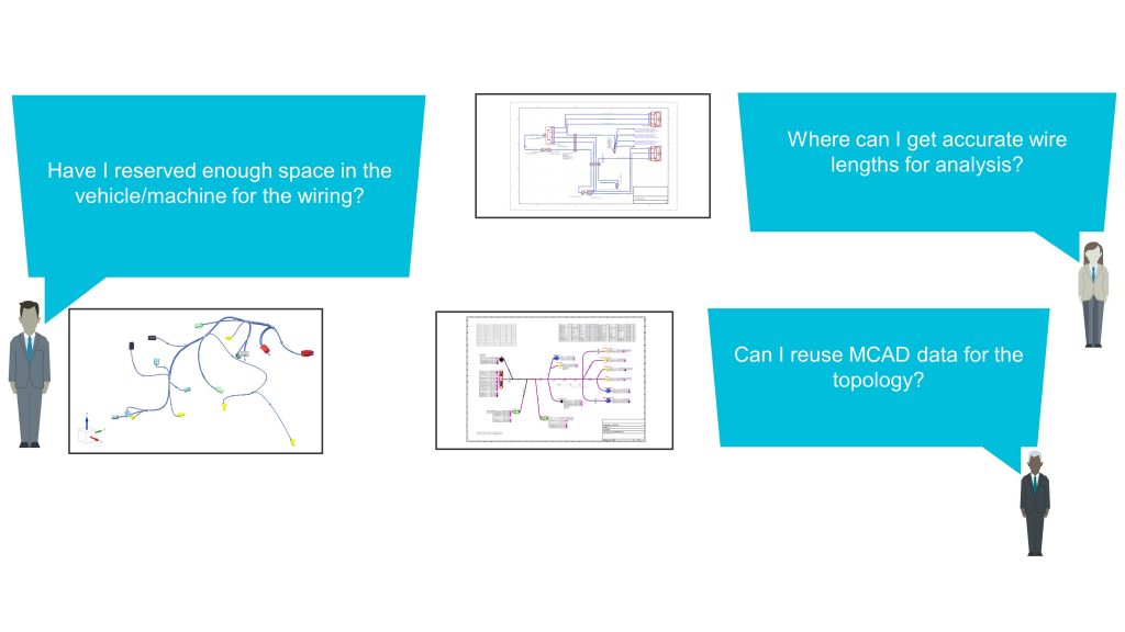
For example, mechanical designers need to verify the physical space constraints of the harness. These will be affected by the bundling thickness and, therefore, the finalized wiring content (Figure 1). Similarly, electrical designers rely on real-world wire lengths to conduct voltage drop analysis and fuse sizing calculations to ensure the correct circuit behavior. And harness designers needs to reproduce the 3D harness topology in 2D and combine it with electrical data. If the 2D harness is just a derivative of the 3D harness, why should it need to be recreated from scratch?

Figure 1. Electrical and mechanical designers are often isolated from critical information contained in the other domain (Siemens EDA)
Modern tools address today’s challenges
New E/E systems and wiring harness tools address the challenges of modern electrical systems design by facilitating collaboration to reduce design costs, cycles and risk.
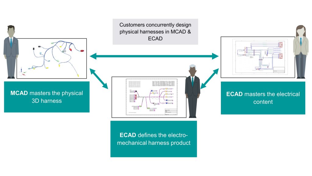
A design flow incorporating modern tools, such as VeSys from Siemens Digital Industries Software, supports collaboration and concurrent design between the electrical and mechanical domains (Figure 2). The mechanical designer defines the harness geometry and fixtures, and reserves space for it in the vehicle or machine. Meanwhile, the electrical designer masters the electrical content for the system, creating the necessary wiring diagrams and conducting analyses along the way. The mechanical and electrical disciplines can work independent of each other, but can also easily pass data back and forth as it becomes available. Then, the harness designer combines the MCAD and ECAD data to fully define the electromechanical harness product.

Figure 2. Digitalization allows electrical and mechanical domains to work closely together with greater insight (Siemens EDA)
These interactions enhance the visibility between the ECAD and MCAD domains, supporting the co-design of mechatronic or electromechanical products. As a result, the impacts of electrical and mechanical-specific decisions taken in one domain are better understood in the other, and this improves overall design quality. In addition, the data exchange supported by modern tools eliminates the need to manually transfer data between the environments, saving time and reducing the risk that errors will be introduced manually.
Direct connections remove MCAD-ECAD domain silos
These robust integration capabilities are enabled via two key constructs. First, a framework of cross-domain bridges and adapters handles the exchange of information between MCAD tools and the electrical design environment. Second, APIs from each MCAD application are used to develop plugins that are deployed within the MCAD products. These plugins ensure a seamless integration of the data across the tools. VeSys supports integrations with PTC CREO, Siemens NX and Solid Edge software, and with SolidWorks and CATIA V5 from Dassault Systémes.
With NX and Solid Edge software, an advanced data exchange allows data to be imported and exported in real-time. Elements can also be cross-highlighted for general ease of use and to assist analysis during wiring and harness design. The functionality automatically switches between wiring mode and harness mode exchange as needed within the same application. Any selected objects in the MCAD solution will be cross-highlighted in the electrical diagram and vice-versa. So, selecting a wire in the electrical solution will cross-highlight the corresponding shortest route path and devices that the wire connects to in the mechanical environment.
In-depth example
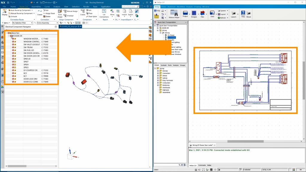
This examples focuses on this exchange of data between the electrical engineer and the mechanical engineer. The wiring information from the electrical and wiring harness solution will be bridged out to the mechanical domain as a wiring PLM XML file. Once the data has been exported to the MCAD tool, connectors will be automatically assigned and wires will be routed, also automatically.
The MCAD design initially contains no electrical content, only the bundles and connectors that have been added by the mechanical designer. A direct connection between the tools is established at the push of a button to enable the real-time import and export of data. In this case, the mechanical designer receives electrical data in a wiring PLM XML file. An integrated filter mechanism allows the user to select the specific harness designs to exchange. The electrical engineer selects just the driver-side door design and exports the electrical content to the mechanical tool. A report shows the number of connectors, splices and wires that were passed.
The MCAD tool is then populated with the electrical data (Figure 3). With this data, the mechanical engineer can automatically assign the needed connectors and manually assign any remaining components, such as splice locations. The automatic assignment of connectors can be done by part number or any other component attribute.

Figure 3. The electrical designer exports wiring data to the MCAD environment (Siemens EDA – click to enlarge)
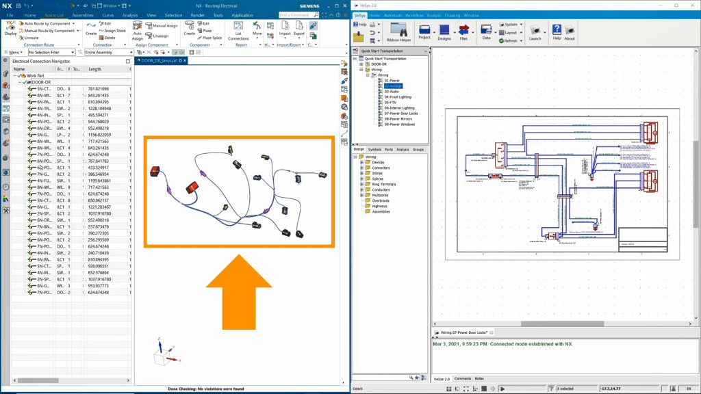
Then, the mechanical designer can automatically route the wires at the component level (Figure 4). The automated flow of data between design tools provides the mechanical designer with all the data required to assign connector part numbers and route wires. As a result, the mechanical designer is able to quickly and accurately replicate the connectivity from the wiring diagram, saving considerable time over manual and error-prone methods.

Figure 4. With the electrical data, the mechanical designer is able to automatically route wiring at the component level (Siemens EDA – click to enlarge)
Now that the mechanical designer has routed the wires in the driver door harness, they have been updated to their accurate lengths according to the three-dimensional constraints of the physical design. This is valuable information with which electrical designers can conduct additional analyses and further verify the electrical behavior. In this example, data now passes from the mechanical solution back to the electrical domain.
With the ECAD and MCAD tools already connected, the electrical designer simply needs to import the data he or she needs from the mechanical environment. As with the export done earlier, a report is provided to describe the data that has been brought back into the electrical environment. All the wires in the ECAD solution are updated with correct lengths from the mechanical design. This allows the electrical designer to perform more accurate voltage drop analysis and fuse sizing calculations.
The power of ECAD-MCAD integration
Digital process transformation is proving ever more critical as products and processes in all industries grow in complexity. Connected and digital tools, such as VeSys from the Xcelerator portfolio, allow companies to develop next-generation products in ever more demanding environments. In particular, ECAD-MCAD integration supports the development of the sophisticated mechatronic products that are in increasing demand. The increased visibility between domains is critical for cross-functional design teams to maximize efficiency. Likewise, advanced automation in both design and the handling of data exchanges gives designers more time to focus on design validation and innovation, both of which improve overall design quality. With both electrical and mechanical portions of the design being of equal importance, fully understanding both aspects will, in the end, result in a better product.
Further reading
To learn more, download the whitepaper “Electrical Design and Wire Harness Engineering”.
 Shane Skinner is a Technical Marketing Engineer working on the Capital, VeSys, and Solid Edge Wiring and Harness Design product lines withom the Integrated Electrical Systems segment of Siemens Digital Industry Software. Shane previously worked for Mentor supporting its PCB design products, Xpedition and PADS. He graduated from Oregon State University with a Bachelor of Science in Electrical and Computer Engineering.

