The necessity and benefits of ECAD-MCAD collaboration for PCB design
Collaboration across the electrical and mechanical domains leverages more tightly integrated and highly featured tools with richer data formats for greater accuracy and shorter time-to-market.
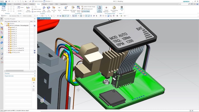
Today, 3D PCB design is the rule, not the exception. Nor can board design take place in a vacuum; it is just one aspect of product design. Designing mechanical elements alongside PCBs and incorporating the mechanical parts for the enclosure, brackets, and heat sinks collaboratively is best done within an ECAD-MCAD collaboration design framework. To achieve all this and deliver the best end-product, a digital model is created within the CAD environment.
Poor electromechanical co-design processes – or a lack of them – account for projects missing deadlines and cost targets by 50% or more. Ignoring the need for electrical and mechanical collaboration throughout your flow results in time wasted fixing costly mistakes, PCB design respins, and missed schedules. This articles looks closely at how modern ECAD/MCAD collaboration works and how it is being used to overcome the challenges this type of co-design presents so that you ‘get it right first time’.
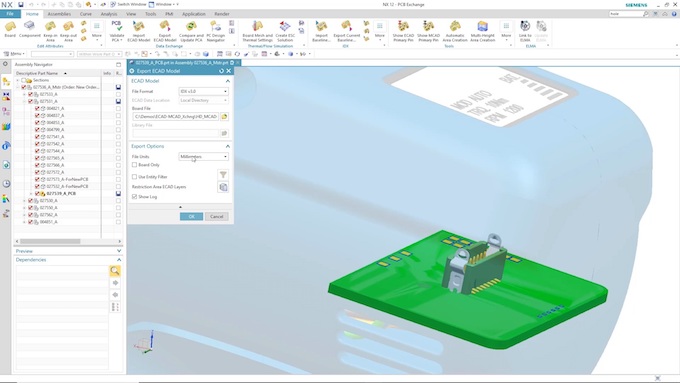
Digital information available from either domain can be shared easily via collaboration applications to that assist in moving in data between tools more quickly, easily and accurately. Such sharing means that electrical engineers can, with a few clicks of a button, import design content created by their colleagues in mechanical engineering. The types of data items that can be shared for ECAD-MCAD collaboration include board outline, component placements, and mounting holes.
ECAD-MCAD collaboration
As the mechanical engineer works through the process of designing that next great product, its electrical part will at some point need to be added. In most cases, the PCB will contain constraints based on the mechanical enclosure. Examples of such constraints include I/O interface connectors, internal structural and mounting features, thermal requirements, and aesthetic features. There are others. Once the design reaches the point where the board outline can be constructed, critical electrical elements can be added to ensure the proper fit. This is where teams can start sharing design content.
Most product design process today involves the creation of a PDF drawing, Drawing Interchange Format (DXF) file, or semi-intelligent Intermediate Data Format (IDF) file. It will include the PCB outline, height-restricted areas, and component locations that the electrical engineer takes as a starting point. Using a drawing or DXF file can allow mistakes to creep through that may not become apparent until the first prototypes are produced. An IDF file adds intelligence by automatically creating the board area, placing parts, and adding the height-restriction areas. However, even here, no design history information is saved and all these approach lack the ability to let engineers make incremental changes between the ECAD and MCAD domains as the design process progresses.
Once the mechanical portion of the PCB is ready for the electrical engineer, you can export an intelligent model in the industry-standard Incremental Design Exchange (IDX) data format. IDX is the next generation of IDF created and is maintained by the industry group ProSTEP IVIP (more information on the standard can be found here). As the ECAD-MCAD collaboration process deepens, design history information is created with tracking of the changes that occur during the development cycle. This can be very useful when a design needs a change to be restored back to a previous state or data is needed for compliance documentation.
ECAD-MCAD collaboration over IDX provides two data-sharing options. First is email, where a file is created and sent to the appropriate engineer(s). The second, and most common option, is directory-based.
Everyone working on a project agrees to use a specific folder that is placed in a shared network location. Each tool is then configured to work from this location every time the collaborative application or platform is used.
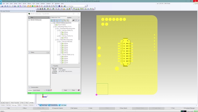
Most tools require the ECAD tool to be in 3D mode before opening the collaboration app. This is required as the collaboration process allows you to review all incoming data. Whether it is a baseline, first import of data or a proposed change, the designer has the option to import all objects or choose only those that are relevant. To assist, the collaboration application should provide preview information that allows the designer to consider what data will be imported. After review, the designer can accept or reject any changes. As seen in Figure 3 below, when the user clicks at the top level of the hierarchy, all objects shown with a selected checkbox are shown. In this case we are starting a design from scratch, so we import the baseline data created by the mechanical engineer.
The next step is to place components that were not placed via the collaboration process. To best place parts on PCBs that are not within a wide-open enclosure, you need to be able to place them in a 3D view. For those not used to working in a 3D CAD space, this may not be the most comfortable way moving objects around.
The issues around 3D components justify an article in their own right. For now, before we move on to placement in that context, a few brief observations.
Quick-rendition 3D models are required to take full advantage of this type of component placement and deliver high quality first-pass designs. Over years of working with customers I have learned that forms of interference between electrical components and mechanical enclosures are one of the top five causes of PCB revisions. Having a proper library capability that allows you to mate (surface, centroid, and axis snapping) and store 3D models dramatically simplifies the design process.
By jumpstarting a design process through the use of ECAD-MCAD collaboration tools, you ensure that all critically constrained mechanical parts are in their proper location. The rest is up to you. However, there is one more aspect of the design process where implementing the mechanical enclosure can be tricky.
To truly ensure no interference fit issues with the mechanical aspects of a design, you need to import all those aspects that may be of concern during electrical design. As for importing and aligning a 3D model for any electrical components, you should be able to import and align mechanical models with the PCB. To simplify alignment, you need intelligent mating functions similar to those all MCAD tools provide. Their features should include surface or face, edge, and axis mating. Model support is important too. Every MCAD tool supports STEP or IGS outputs and your ECAD tool should as well.
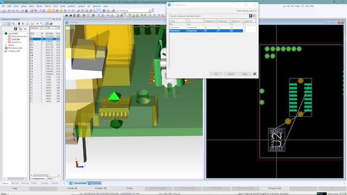
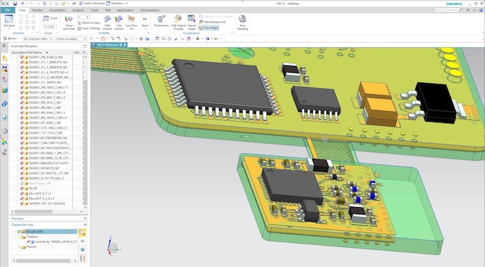
Once the sensitive mechanical models have been imported and aligned, you can move on to placing components. Just as happens when dealing with 2D objects on a PCB, design rules ensure no manufacturing errors are introduced. Placing components should be no different. Design rules (Figure 4) are needed to make sure you do not violate Z-space clearances. This reduces manual and time-consuming visual inspection.
At some point, the mechanical engineering team will want to see the placement. There can be numerous reasons why. These include documentation, simulation, completion of the data model, possible changes, and more. As noted above, one advantage of an IDX data model is its ability to output change-only data. When exporting a design where all or most of the components have been placed, only new or modified items will be highlighted for review in this use model. This reduces the data file-size and the risk of any compare errors occurring. To assist even further with output data selection, filter controls can give you the assurance that only the proper data is transferred. History tracking and change documentation are also critical. Before outputting changes for the mechanical team, you can add notes explaining your intent behind any changes or additions.
The mechanical team is now told that the electrical output is available for import. From their MCAD tool, its members can open the collaboration app, open the new proposal file, and review the proposed changes on the ECAD side as shown in Figure 3. They can then deselect any objects they do not want to import, review notes provided by the electrical/PCB engineer, and import the data. All that is provided with most MCAD tools when placing models from the ECAD side is a simple 2.5D model.
So that real 3D models are placed on the import, the MCAD engineer must create a cross-reference file identifying the ECAD model name to the MCAD model name with X, Y, Z offsets. In an integrated collaboration flow this process is not required. Take the case of Mentor’s Xpedition or PADS Professional used in conjunction with Siemens NX. All electrical component 3D model data can be exported via the collaboration app and automatically imported to NX. This saves time-consuming cross-reference file creation and maintenance.
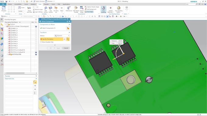
So, let’s consider this ECAD-MCAD collaboration example. A mechanical engineer is looking at a future change and wants to make sure the PCB will not need revising. Specifically, he or she would like to move a component inward on the bottom of the PCB. Instead of relaying this information to the electrical engineer and dealing with back-and-forth iterations until everything is correct, the mechanical engineer can move the part or parts and output a new proposal with notes as to why he or she thinks the change is required.
From the ECAD view, the electrical engineer can graphically consider the changes and review the notes before importing. If he or she finds assembly issues in the change, the proposal can be rejected, an explanation provided and a new location proposed. In this example though, the proposal is sound and the project moves forward based on acceptance from the ECAD side. The mechanical engineer receives an acceptance file confirming that approval.
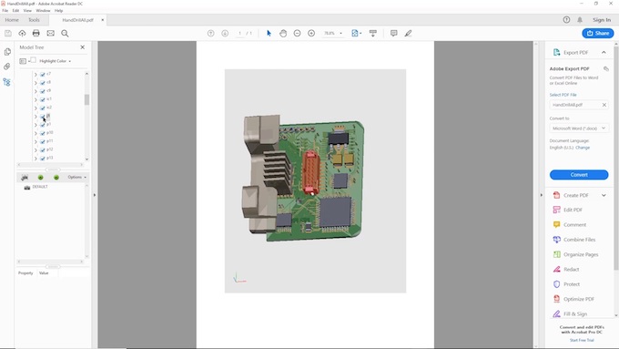
But what do you do if your MCAD tools do not support the ProSTEP IDX exchange format? You have the option of using IDF, as discussed earlier, or STEP, the industry-standard 3D data exchange format. This method does not provide as much intelligence but can still assist on the PCB side with board-outline creation and mounting-hole location. On the electrical side, you need to know that your ECAD tool can export STEP so that any MCAD tool can view a 3D PCB. To facilitate ECAD 3D documentation, industry-standard formats need to be available, like 3D PDF, STEP and SAT.
Creating a digital model from ECAD through to MCAD allows you to perform simulations on designs that would normally need to be built as prototypes, a time-consuming and more onerous approach. For mechanical analysis like thermal, shock, vibration and environmental, reproducing or cleaning up data has always been a lengthy task. Thanks to the option for IDX collaboration, you can now transfer a full electrical model to most mechanical tools.
ECAD-MCAD collaboration benefits
Collaboration between design disciplines has become mandatory for design teams to meet today’s tight product design schedules. Visualizing and using design content created by other colleagues and disciplines across the project team enables faster delivery and allows you to make better decisions. Changing your design philosophy is always challenging but continuing to use obsolete tools and methods will allow your competitors to be first to market.
Benefits from intelligent collaboration include:
- Reducing design time through the use of ECAD/MCAD collaboration features in tools like PADS Professional or Xpedition;
- Eliminating costly mistakes and design spins through the use of 3D placement;
- Exploring new ideas that might allow you to add more advanced features and capabilities; and
- Producing a higher quality product.
ECAD tools like PADS Professional or Xpedition include powerful, easy to use ECAD-MCAD collaboration features that allow electrical and mechanical engineering teams to work together more efficiently, and thereby deliver better products in less time. Engineers can seamlessly share data while continuing to work within the CAD domains that are familiar to them. Costly design spins are eliminated by catching issues that slip past less efficient, traditional methods.
Today’s complex products are no longer just a PCB. They are complex electro-mechanical systems consisting of multiple PCBs, thermal solutions and mechanical enclosures and demand this kind of flow integration and collaboration.
For more information, watch this webinar ‘Electro-mechanical Co-design for Competitive Advantage’, or book a fully-functional free trial of PADS Professional.
About the author
Brent Klingforth is a Technical Marketing Engineer at Mentor, a Siemens business. He specializes in schematic, PCB, and manufacturing products and has more than 25 years of experience in PCB design. Brent is IPC certified and before joining Mentor worked as an application engineer and a PCB designer.
