High-level synthesis for AI: Part Two
Part One of this series looked at how high-level synthesis can be used on AI-led design projects, with particular reference to computer vision. This second part discusses how to use HLS with reference to a specific project.
That project is the development of a block of computer vision IP at Chips&Media (C&M). It is described in more detail in this technical article.
The c.WAVE100 IP detects objects in real-time based on a 4k resolution captured at 30 frames-per-second. The detection algorithm comprises MobileNets, single-shot-detection and proprietary optimization.
The deep neural network is trained, refined into a C model on the open-source TensorFlow framework and targeted for synthesis into RTL.
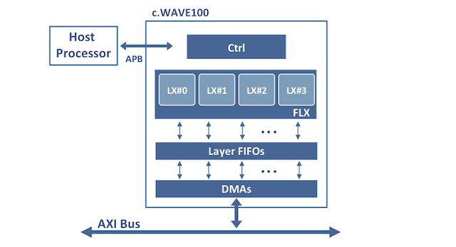
Figure 1 shows a block diagram of the hardware IP.
It contains four layer accelerators. LX#0 and LX#2 are neural network layers that employ conventional and depthwise convolution. LX#1 and LX#3 are neural network layers that employ pointwise convultion. The pointwise layers carry a much higher computational load (87% of all the multiply and accelerate processing units).
The consequent need to optimize area and resources drove C&M toward the adoption of HLS using the Catapult platform from Mentor. C&M needed an environment that gave it the greatest latitude for architectural exploration. This is a common issue in AI-led design today as the sector matures.
Similarly, C&M decided that it needed to deliver a hardwired IP because of how the demands of computer vision now test the performance, power and area capacities of traditional platforms and common programmable IP.
The HLS flow
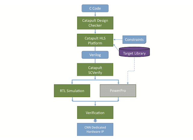
Figure 2 shows the flow that C&M used (though with the PowerPro power analysis capability of the Catapult suite greyed-out as it was undergoing evaluation during this project).
Key HLS elements of the flow include:
- The use of the Catapult Design Checker to apply static and formal verification before RTL simulation and based on its ability to check C code without a simulation framework.
- The use of the Catapult HLS Platform including the synthesis of pointwise layer algorithms hand-coded in C then synthesized to Verilog following the addition of constraints and target library information.
- The use of the Catapult SCVerify feature for automated verification, partly in the form of a ‘push-button smoke test’. This feature automatically sets up co-simulation of untimed C and the resulting synthesized RTL.
Results
Given that this was C&M’s first use of HLS, the company ran the development of hand-coded RTL and HLS-synthesized RTL alongside one another for comparison.
Some of the key results of the comparison were:
- Development: 5 months for the hand-coded RTL flow vs 2.5 months for the HLS flow (including the adoption of Catapult).
- Area: 1,230K gates and -0.51ns slack time for RTL flow vs 1,439K gates and -0.14ns slack time for HLS (although C&M considered these equivalent based on gate count for the ‘core operation).
- Synthesis runtime: 10 hours for the flow RTL vs 5 hours for the HLS flow.
- Gated registers: 95.05% for the RTL flow vs 97.5% for the HLS flow.
In some areas, RTL did have some advantages. For example, the RTL flow did offer “a few more percentage points” more in performance. But, C&M believes that “the gap can be reduced or even overtaken with more changes to the architecture.” One of the advantages of HLS is that it enables greater architectural exploration within tight time budgets.
“At the conclusion of the project, we ended up using the HLS-coded design for the final IP. The HLS approach was easier to synthesize into Verilog, debugging was much faster than RTL simulation, and timing closure was less painful than the traditional RTL approach,” write Mickey Jeon and Knight Kim in C&M’s technical paper.
The company is now using an HLS flow to develop a DNN-based Super-Resolution block for computer vision.
 Paul Dempsey is editor-in-chief of Tech Design Forum
