Part 4- Power management in OCP-IP 3.0
According to Moore’s Law, system-on-chips (SoCs) should continually become more complex and integrate more components, enabled by each reduction in silicon technologies. However, power consumption does not follow the linear path implied here due to increasing leakage in deep sub-micron technologies. Hence, new power management techniques are needed to reduce power dissipation as much as possible.
This paper explores how to address architectural challenges seen in today’s complex SoC designs based on the Open Core Protocol (OCP) by taking advantage of such techniques. The concept of interface disconnection is introduced and the OCP disconnect protocol is described, based on its implementation described in the 3.0 release of OCP-IP. Finally, we consider several implementations in a power management framework.
A typical system-on-chip (SoC) can be partitioned into several domains that will be more or less independently managed with respect to power consumption. Several techniques may be used such as lowering the clock frequency, lowering the voltage, gating the clock, entering a retention mode or completely powering down the device. This list is not exhaustive and a full review of power management techniques is not our purpose here. However, one must realize that with some of these techniques, the affected components are not responsive to any input. At most, signals from such components can be forced to a predefined value using a clamp technique, and these enforced states will be referred to as ‘sleep’ states for the rest of this article.
The Open Core Protocol (OCP) defines a point-to-point fully synchronous unidirectional interface protocol that can be used as an internal communication method. The protocol is pipelined, with transfers made up of three phases: request, data and response. It supports multiple transaction types from single access to 2D burst, including support for threads and tags. Its main attribute is its high configurability, OCP being both modular and scalable. A further important aspect to note is that the protocol does not support retraction: a request phase cannot be aborted.
Source: Texas Instruments
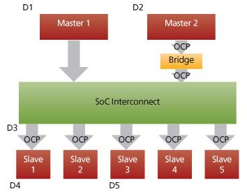
FIGURE 1 Simplified SoC architecture
Figure 1 shows a simple SoC that uses OCP for the interconnect. It includes several domains. D1 and D2 are labeled as master domains as they include at least one master OCP interface at the boundary. D4 and D5 are labeled as slave domains as they include at least one slave OCP interface at the boundary. D3 is both a slave and a master domain according to the previous definitions. An OCP-to-OCP bridge is also shown. Its purpose is to adjust different clocking rates or different socket characteristics between a master domain and a slave. The bridge can be fully synchronous or asynchronous, and can include internal FIFOs to temporarily store transactions.
Putting a domain to sleep
Before putting a domain into a sleep state, all OCP transactions that cross the domain boundaries must have been completed. If this is not the case, various problems can arise. For example, if a domain starts being put into sleep with outstanding transactions at its boundary, the corresponding communicating entities will likely become stuck or corrupted. Such disorders may then propagate via the interconnect throughout the entire SoC. There is no easy way by which to recover from either of these scenarios, if at all.
Intuition suggests that software could be used to guarantee that such a necessary condition is fulfilled before the sleep transition is performed. However, software-based transaction monitoring is extremely difficult—if not impossible—in complex SoCs that have both multiple masters and a complex interconnect. Moreover, some masters operate in such a way as to be, in effect, totally independent of software, an example being a debug master IP.
Bridging
To determine the safe conditions under which to put a domain into sleep where there is a bridge involved, you need to know if that bridge is located in the master domain, the slave domain or split across both. The exact conditions may be hard to define, especially where a bridge is split across two domains. From an architectural point of view, it is more practical to consider the bridge and the two OCP interfaces (master and slave) as a unique OCP socket, and then apply similar conditions across them before performing a sleep transition. By this measure, one domain linked to another through an OCP-to-OCP bridge can only go to sleep if:
- OCP transactions are completed on OCP interfaces with both the master and slave domains and none is outstanding; and
- the bridge is empty of transactions (here, the bridge is said to be ‘fully drained’).
Traffic toward a sleeping slave domain
Even after one domain has been properly put to sleep, a still-active master may still try to send transactions toward it. These will probably induce the same kinds of disorder discussed earlier. Again, you cannot rely upon avoiding this by using software. So what are your options?
The OCP disconnect protocol
The OCP disconnect protocol aims to address these problems. It is an optional add-on in version 3.0 of the OCP-IP standard and is based on the concept of alternative ‘connection’ and ‘disconnection’ states. Connection is a state where both sides are functional and where communication can happen normally. Conversely, disconnection is a state where no communication is possible, and is instituted by a clean termination of the communication interface. Given these definitions, the disconnection state becomes a prerequisite for all OCP interfaces at a domain boundary before they are put into a sleep state. The disconnection protocol is based on the following principles:
- The transition to connection or disconnection is performed in the master.
- Both the master and slave ‘vote’ as to whether to enter the connection state or request disconnection.
- Both the master and slave can temporarily stall the transition being performed at the master.
- The slave’s vote and a stall directive are propagated to the master side.
- The master generates the actual connection status and propagates it back to the slave, in agreement with both domains’ votes and any stall directives, underlining the need for a clean termination.
- OCP transactions can be issued only by the master and only when the master is in the connection state.
- The slave is committed to handling transactions normally while still in the connection state, independent of its own vote.
The voting mechanism allows a connection to be established only where there is mutual agreement. It is better to perform the connection or disconnection at the master side as, where an OCP-to-OCP bridge is present, this allows the emptying/idling operation for that bridge to be part of a disconnection process. It is assumed here that the bridge understands the OCP disconnect protocol.
The master generates the actual connection status and propagates it to the slave. The slave monitors this connection status to determine when it is safe to perform a domain sleep transition. The connection status permits a disconnection state initiated solely by the slave to be distinguished from a disconnection state initiated by the master. In the case of a disconnection state initiated solely by the slave, the protocol supports an alternate behavior of the master port for new traffic intended for the disconnected slave. This alternate behavior is not in the scope of the specification, but can take various forms depending on other architectural choices (e.g., default error response, default data valid access response, wake-up on-demand). The signals used by the disconnect protocol are shown in Table 1.
Source: Texas Instruments
|
Signal |
Value |
Description |
|
MConnect [1:0] “Connection status” Driven by the master |
‘b00 (M-OFF) |
This is a disconnect state, requested by the master. The OCP interface is cleanly stopped. The alternate behavior is also cleanly stopped. This is the default reset state. |
|
‘b01 (M_WAIT) |
This is a transient state. The OCP interface is cleanly stopped. The alternate behavior is also cleanly stopped. |
|
|
‘b10 (M_DISC) |
This is a disconnect state, requested solely by the slave. The OCP interface is cleanly stopped. The master alternate behavior is enabled. |
|
|
‘b11 (M_CON) |
This is only connection state. The OCP interface is up and running. It can send transactions to the slave. The alternate behavior is cleanly stopped. |
|
|
SConnect “Slave’s vote” Driven by the slave |
‘b0 (S_DISC) |
The slave is either requesting a disconnect sequence, or once disconnected, indicating it is unwilling to re-connect. This is the default reset state. |
|
‘b1 (S_CON) |
The slave is indicating a readiness to perform a re-connect sequence, or maintaining a connected state. |
|
|
SWait “Slave’s stall directive” Driven by the slave |
‘b0 (S_OK) |
Used to indicate to the master that transition to any new state is allowed. This is the default reset state. |
|
‘b1 (S_WAIT) |
Used to indicate to the master that it can only transition to the M_WAIT state. That is, the slave temporarily stalls the transition at the master side. |
TABLE 1 OCP disconnect protocol signals
Source: Texas Instruments
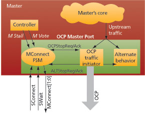
FIGURE 2 Master high-level architecture
Connection status FSM
A finite state machine (FSM) is responsible for generating the OCP connection status at the master side (Figure 2). It controls both the OCP traffic initiator and the alternate behavior of the OCP master port, based on simple request/acknowledge full handshakes. It also interacts with the master controller that provides the connection vote and the stall directive (‘MVote’ and ‘MStall’). Finally, the FSM is connected to the slave via the interface of the OCP disconnect protocol (Figure 3).
Source: Texas Instruments
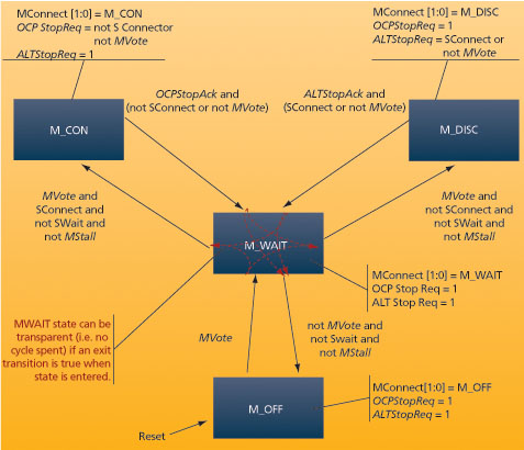
FIGURE 3 Connection status FSM
Linking the OCP disconnect with power management
As discussed above, the OCP disconnection state is a prerequisite for all OCP interfaces at a domain boundary if a domain sleep transition is to be performed. Figure 4 shows an implementation where the global power manager has a dedicated power-management protocol with the managed entities, specifically a ‘SleepReq’/’SleepAck’ handshake.
Source: Texas Instruments
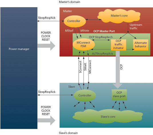
FIGURE 4 Link with power management
Before transitioning a master domain into a sleep state, the following sequence must be followed.
- The power manager sends a sleep request to the master.
- The master controller initiates its internal shut-down sequence.
- The master controller votes for an OCP disconnection.
- The connection status reaches the ‘M_OFF’ state.
- The master controller acknowledges the sleep request.
- The power manager carries out the sleep transition.
Similarly, before performing a slave’s domain sleep transition, this sequence must be followed.
- The power manager sends a sleep request to the slave.
- The slave controller votes for an OCP disconnection.
- The slave controller waits for an OCP disconnection state (‘M_DISC’ or ‘M_OFF’).
- The slave controller proceeds with other internal shut down operations, if necessary.
- The slave controller acknowledges the sleep request.
- The power manager carries out the sleep transition.
In the same way, a sleep sequence can be defined for an interconnect IP that consists essentially of the combination of the two above use-cases because an interconnect IP is both a slave and a master. Upon a sleep request, the internal controller first disconnects all the OCP slave ports, then it drains out all remaining internal transactions. Next it disconnects all the OCP master ports, and finally it acknowledges the request.
Cases where an OCP-to-OCP bridge is present between the master and the slave can also be handled smoothly thanks to the OCP disconnect protocol. The latter can be conveyed through the bridge and the disconnection state can be gated by the bridge emptiness state. Furthermore, coherency properties can be satisfied between both sides of the bridge. The two OCP sockets plus the bridge are then abstracted to a single OCP socket from the power manager’s point of view; the bridge is transparent to it.
Conclusion
There is a clear trend toward the use of more and more power management techniques within SoCs. As part of this process, multiple domain partitioning presents new architectural challenges. The OCP disconnect protocol has been introduced to facilitate power management transitions at the domain level. Gating the domain sleep transition by a prior OCP disconnection state ensures that the system will remain coherent and will not experience any disorder due to the OCP interfaces.
OCP International Partnership
3116 Page Street
Redwood City
CA 94063
USA
T: 1 512 551 3377
