Emulation delivers system-level power verification
Overcome the time and visibility limitations of simulation and of gate-level and RTL-based strategies to achieve full-chip analysis.
Emulation has become the necessary system-level low-power verification and power analysis technique for today’s SoCs. It allows engineers to make truly informed decisions based on views of the full chip.
Emulation alone can apply real-world stimuli and very long tests. However, because of the length of these tests and other factors, the emulators must possess certain capabilities to accurately and fully verify power management techniques and analyze power characteristics.
Fully capable emulators, such as Veloce from Mentor Graphics, allow designers to pull in the full design environment for even billion gate designs. They use actual stimuli, including application and embedded software, and allow designers to run many sequences. None of these is practical or possible in simulation.
Verification and analysis of power characteristics and functionality had been addressed first at the gate level, then at the RTL. Both approaches fall short for system-level verification and where applications require real-world inputs.
Gate-level verification poses many issues. Simulations are slow, debug is difficult, and it takes longer and requires more resources to resolve functional problems. RTL simulation using directed unit-level tests on individual blocks provides neither the completeness nor accuracy required for full chip power verification and analysis.
System-level verification is now also critical because power is impacted by both software and hardware. For example, because the power ON/OFF controls for power domains come from application-level software while the control logic resides in hardware, engineers must verify power-aware aspects of a design at the system level where both software and hardware can be assessed side by side.
An emulation-led system level power solution has two main aspects: power-aware verification and power analysis.
Power-aware verification ensures that power management techniques have been properly implemented and that the power functionality is correct. The technique uses emulators running software and hardware simultaneously. Test sequences are sent from software and then executed by the hardware. As a result, designers can also boot an operating system and stress test the design through a very large number of power sequences extremely quickly.
Power analysis calculates average and peak power to help design efficient batteries and to avoid such things as over- or under- specifying SoC power requirements. The technique uses emulators to provide a platform where engineers can accurately calculate average and peak power. Emulation can run application-specific traffic for potentially billions of cycles, collect the data, and compute the two metrics. The results are much closer to actual power consumption than is possible with simulation or manual calculations.
These techniques can be used together or separately.
Emulation for power-aware verification
There are various ways to reduce power consumption and thereby increase the lifespan and reduce the size of a battery. Designs are divided into different power domains where management techniques turn various segments on and off. The domains are based on areas of functionality that support common operations or tasks. Power control signals are used to control sequential retention cells, isolation cells, and the switches that serve as gatekeepers to a domain’s power supply.
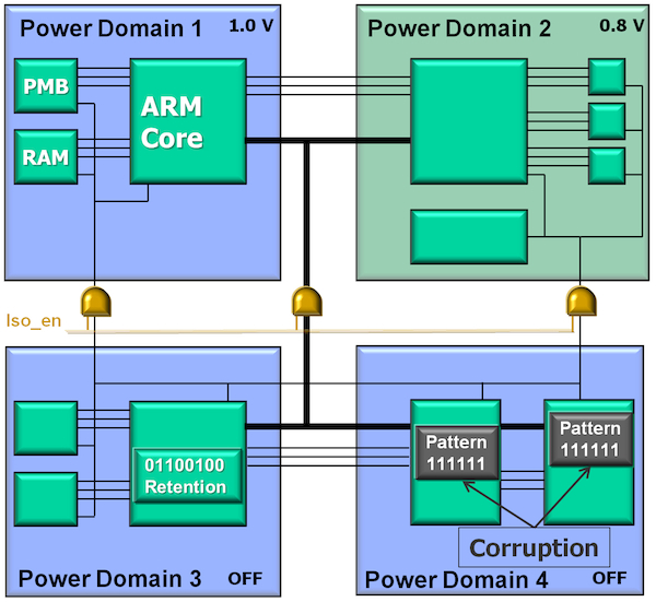
The rising number of power domains in SoCs is a major reason why emulation has become essential to complete accurate power-aware verification. With tens of power domains in a single SoC, verifying the low-power functionality becomes very expensive in simulation. Only emulation has the speed and capacity to repeatedly exercise a large number of power domains. Because the whole SoC is mapped into the emulator, it can mimic low-power retention and functionality using real stimuli, providing much higher confidence in the completeness of the verification.
Figure 1
Power-aware functional verification using Veloce (Source: Mentor Graphics – click image to enlarge)
Four power management techniques must be thoroughly verified as part of power-aware verification:
- Retention.
- Corruption
- Isolation logic.
- Multiple voltage levels.
Retention
Retention flops and latches (or other retention strategies) ensure that power domains return to a known-good state when powered up or down. Retention cells are expensive so designers seek to insert the minimum number necessary to retain critical states in a design. Because emulation runs long tests using actual application stimuli in the full design environment, it can verify that a design behaves correctly after insertion of the retention states specified by the user.
Corruption
Simulation solutions model corruption by forcing an X value, but emulators are typically two-state systems. Emulators like Veloce provide four kinds of corruption models: all 0s, all 1s, invert of current state, and pseudo random corruption. When a domain powers off, one of these corruption semantics will be applied on all the states in the switched-off domain and will verify that the design still works correctly. With run-time control, designers can choose between the four models for increased corruption coverage. Dynamic assertions are inserted to check for specific cases. Assertions help to quickly locate the root cause of low-power failures during an emulation run and do not require the user to specify where to look for potential failures. Corruption models and assertions increase confidence that the design will work correctly when the chip is fabricated.
Isolation logic
Isolation logic gates determine the values of a power domain’s input or output port when the domain is powered down. Even though they may represent different power domains that can be independently powered on and off, the corresponding areas of silicon remain physically connected. Therefore in silicon, when one domain is turned off, it is still connected electrically to other domains. Emulation-based power solutions allow SoC designers to verify that isolation cells are inserted at all the required locations and that they drive correct values during a domain’s power-off state to prevent corruption of downstream active logic.
Multiple voltage levels
Because higher voltage means higher power consumption, designers want to use lower voltages whenever possible. But certain portions of a design may need to run at a higher clock speed. So, designers create multiple voltage domains to meet specified power budgets and insert level shifters to ensure that a logic 1 in one domain is recognized as a logic 1 in another downstream.
The power verification tool needs to verify three aspects about these level shifters:
- They exist in all the required locations.
- They have the right polarity.
- They are within the right voltage up and down range.
Compiled in the emulator along with the design RTL, assertions that are inferred automatically ensure that each level shifter is correct in all three aspects.
Along with modeling solutions for retention, isolation, corruption, and multi-voltage domains, emulation provides debug solutions to identify the root cause of a power-related emulation failure and highlight low-power design bugs quickly. Just as with level shifters, dynamic assertions are automatically inserted and synthesized to check for unexpected conditions, such as a corrupted value on a retention state or the propagation of a corrupted value from an off to an on domain due to an inactive isolation cell.
Emulation for power-aware verification
Power analysis requires capturing realistic average and peak power consumption. These can be determined only by applying application-specific stimuli. The technique also requires running long tests to ensure that actual power peaks are captured. Neither of these can be done at the block level. Simulation can run for a few tens or hundreds of thousands of cycles and calculate average power, but such a small sample cannot produce an accurate result.
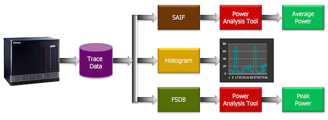
Figure 2
Power analysis using Veloce (Source: Mentor Graphics – click image to enlarge)
The two key aspects of power analysis (Figure 2) are average power and peak power.
Average power
Average power is a key predictor of battery life for an application or SoC. Emulation ensures the accuracy of average power calculations by running real-world stimuli over hundreds of million cycles. Emulation systems then produce a Switching Activity Interchange Format (SAIF) file for the average power computation, based for Veloce on the IEEE P1801 Unified Power Format (UPF) standard.
The SAIF file contains the switching activity of all the states in the design, as well as the design’s primary inputs and power critical signals. This file can be supplied to any standard power analysis tool for the average power computation.
Because the information in the SAIF file is reflective of the actual stimulus used in the final design, rather than on directed tests or short tests generated in simulation, the resulting average power consumption numbers are much closer to the actual power consumption of the SoC when it is fabricated.
Peak power
Peak power analysis begins by determining where and when to look for hot spots in a design that runs for billions of cycles. Certain emulation solutions, such as Veloce, address this using a sub-sampling approach, which can be used to accurately and quickly identify actual power peaks and hot spots in a design.
As for average power computation, this approach captures the toggle activity on the states in the design; the difference is that it does not capture the toggle activity on each clock cycle but uses a user-defined sub-sampling ratio. The peak areas of interest are now narrowed down to a few hundred thousand or a million cycles. Designers can then do much more accurate and detailed power analysis on those peak areas of interest by sampling on each clock edge, creating a file system database (FSDB) or SAIF file. These files now can be fed to any power analysis tool for more accurate and detailed peak-power analysis.
A peak power of interest will typically occur after the boot operation, which in itself is a long operation. In this case, the emulator executes the booting operation at mega-hertz speeds without capturing any of the state-level activity. So the operating system boots in only a few minutes. Once emulation reaches a peak power area of interest, the user enables full sampling, which starts capturing the state-level activity and generates the FSDB or SAIF file for the power analysis tool.
Conclusion
Because emulators can run billions of cycles of real stimulus to identify actual hot spots and power consumption, users avoid making false assumptions about the power consumption of the SoC. Emulation speed enables them to run power analysis several times before they tape out a chip to verify the changes made in the RTL code or the power control logic. This is not possible with simulators.
About the authors
Vijay Chobisa has 12 years of experience in transaction-based acceleration and in-circuit emulation. He is the Product Marketing Manager for the Mentor Graphics Emulation Division. He has worked as a technical marketing engineer and technical marketing manager at IKOS systems and as an ASIC design engineer at Logic++. Vijay holds a bachelor’s degree in electronics and communication engineering from Jai Narayan Vyas University, Rajasthan, India.
Sanjay Gupta has over 20 years of EDA experience related to emulation, transaction-based acceleration, and RTL synthesis. He is currently Group Engineering Director with the Mentor Graphics Emulation Division and a lead architect for the Mentor TBX transaction-based acceleration solution. He has been involved in IKOS and Mentor Graphics emulation product R&D for the last 15 years.
Contact
Mentor Graphics
Corporate Office
8005 SW Boeckman Rd
Wilsonville
OR 97070
USA
T: +1 800 547 3000
W: www.mentor.com


