Keeping high-speed designs clean with ERC
Electrical rule checks (ERC) are now available to deal with increasing PCB design complexity, speed project delivery and protect the intellectual property within them.
Designers must confront faster clock speeds and driver edge rates, increasing net densities and a growing number of constrained nets.
There are numerous challenges to ensuring a ‘clean design’. They include signal integrity, reliable timing, well behaved waveforms, acceptable crosstalk, adequate power distribution, and electromagnetic interference (EMI) levels that meet global regulatory requirements. These can no longer be overcome by using outdated design methods and procedures that lack adequate simulation coverage, and performance verification techniques that jeopardize first time design success or profitable performance yields.
Everything matters
For today’s high-speed designs, everything matters. That includes the electrical performance characteristics of the connectors, the properties of the PCB interconnect and dielectric, the test and measurement setup, and of course the design tools employed.
Many designs use leading-edge FPGAs to target 40G/100G Ethernet applications. Others use multi-GHz microprocessors for laptops and tablets. And often, they incorporate DDR2/DDR3 wide bus memories. All require very dense interconnect implementations with lightning fast signals. The ‘Everything Matters’ world of design demands an approach that quickly and accurately checks electrical performance robustness as schematic and layout design proceeds.
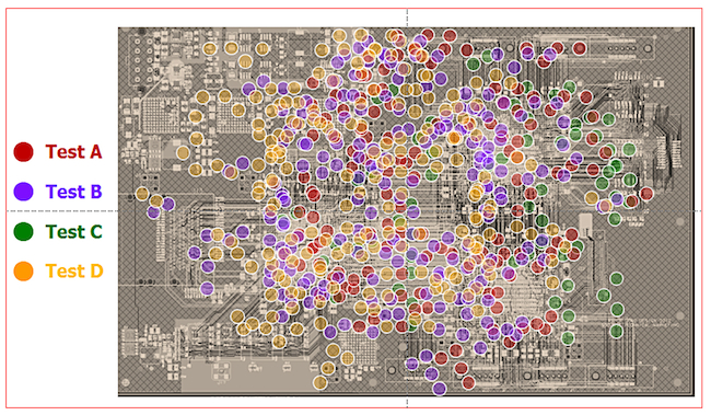
We can think of such a capability as synonymous with a yearly health checkup that includes X-rays/MRIs and various other tests. Those tests help lead to a diagnosis and hopefully a remedy or care plan to rectify any problem. The equivalent for PCB design is an EDA tool that runs appropriate tests on a layout to identify potential electrical rule violations so that more in-depth simulation and analysis can be proscribed to prevent catastrophic design flaws slipping through the final sign-off gate (Figure 1).
Figure 1 PCB design performance checkup results (Source: Mentor Graphics)
Design intellectual property
In their efforts to manage complexity, teams rely heavily on master designers with extensive experience and know-how. They help to develop sets of guidelines, blueprints for success that can be carefully followed throughout the design process.
Many companies consider this special design knowledge and know-how proprietary. Often, they consider it to be among their most sensitive intellectual property (IP). Converting this IP into usable guidelines poses several challenges and risks.
It end-users typically have a broad range of skills and understanding themselves that must be considered during guideline development. The guidelines must avoid any ambiguous and be complete. Nevertheless, the intent of the master designer is often misunderstood or the rule is applied incorrectly. This issue is further complicated once individual design/CAD teams need to interpret and derive actionable physical and electrical design rules to be followed during circuit design and layout.
Physical design rules tend to be straightforward. They often deal with common routing issues like trace spacing, width, via clearances, and so on. Constructing electrical rules can be more challenging.
Each electrical rule has an impact on the final geometrical layout but is based upon a much deeper understanding of the electrical behavior of certain physical representations. Electrical rules are intended to help the layout team avoid inadvertently creating EMI, electromagnetic compatibility (EMC) and electromagnetic coupling. They are also meant to ensure signal integrity (SI) and power integrity (PI). As one would expect, arranging, say, the physical layout of components, signal interconnects, and power planes to comply with electrical rules is not intuitive. It usually depends on visual inspection and measurement to confirm rules are being followed.
As in-house guidelines are more and more frequently augmented by others from targeted IC vendors, many resulting designs are ultimately coming to include some significant deviation from the combined rules in one way or another. As design complexity and performance increase, the risk of such deviation also logically increases. Senior managers struggle with this dilemma every day.
Electrical rules-driven performance verification
Faithfully following electrical rules derived from design guidelines provides an adequate, but not always mandatory, condition for a successful design. Often, design tradeoffs exist where overdesign to meet one rule saves enough design margin for another rule to pass without violations.
This common occurrence may lead you to believe that not all guidelines are necessary and that some may even mask the real performance condition of the design. The goal for any electrical rule checking (ERC)-driven performance verification flow should be to verify if overall electrical performance meets expectations, not the enforcement of each individual physical routing rule.
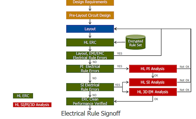
One new approach to consider is a design flow that allows design teams to ‘DARE’ – that is, to easily Detect, Analyze, Repair, and Evaluate potential electrical design flaws early and often as the layout hardens (Figure 2).
Once the design requirements have been determined and pre-layout circuit design starts wrapping up, layout begins. Here, performance-critical portions of the design can be among the first layout structures to be checked and verified against performance objectives. Using HyperLynx ERC early and often to guide layout designers towards performance-friendly physical implementations will reduce the rework required as more of the layout topology hardens.
Running ERC to detect potential performance design flaws enables the layout team to iterate immediately as they seek to resolve issues through layout alternatives. However, some SI/PI design flaws do require a deeper understanding. These are candidates for simulation under HyperLynx SI, HyperLynx PI, or HyperLynx 3D EM to analyze and quantify the severity of the violation.
Critical design flaws are then flagged and passed back to the layout team for further repair. This simulation triage process continues as the layout matures and until all ERC violations have been addressed either through layout repair or an engineering-led violation mitigation design practice. At that point, a final performance evaluation ERC run should be run as part of larger electrical rule signoff procedure to double check that no catastrophic flaws have been missed.
Figure 2 ERC-driven performance verification flow (Source: Mentor Graphics)
Adopting this type of ERC-driven performance verification methodology truly reduces the chances of hard-to-detect electrical design flaws passing manufacturing signoff. Furthermore, overall design quality is improved as are design performance margins. And every design still benefits from a master designer’s quality review before release.
Keep it clean with ERC
ERC not only helps improve simulation coverage, but also provides a secure method for capturing and applying sensitive master designer know-how.
The Mentor Graphics HyperLynx ERC tool helps keep designs clean of hard-to-detect electrical design flaws. It supports custom rule definition using standard scripting languages.
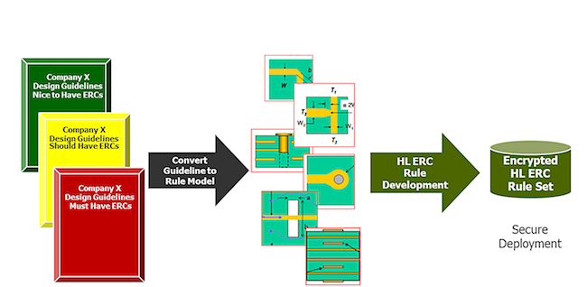
Rule developers leverage work converting design guidelines to actionable layout rule modes by capturing intent in the form of programmable electrical rule descriptions. The IP contained within each description can be encrypted, locking the contents from outside tampering. The encrypted rule set can then safely be shared with internal design teams or with business partners and customers (see Figure 3).
Figure 3 Secure deployment of electrical rule sets (Source: Mentor Graphics)
Encryption opens the door for ERC developers to consider enriching rule sets with sensitive design know-how in the form of algorithmically-rich computational light rules. This fills a gap between those design teams that do not use any simulation tools and those that rely on SI/PI experts for help with performance verification. In the former case, design teams lack the expertise to adequately operate sophisticated SI/PI tools but do desire to improve design performance predictability. In the latter case, there typically are not enough SI/PI experts available to the team or enough time to exhaustively simulate the entire design.
These performance indicator rules are really lightweight analysis engines. They are not intended to replace the SI/PI analysis tool, but rather to be used to better screen potential electrical design faults by reporting a quantitative measure of ‘goodness’ against SI/PI metrics. Faults detected by these types of rule sets help the design team focus on precise locations that warrant deeper SI/PI simulation and analysis. Or better yet, they can direct the layout team to iterate, attempting to resolve violations through alternative layouts without requiring help from an SI/PI expert.
Only rule violations that cannot be resolved through layout iterations reach the SI/PI expert, where deeper simulation and analysis is applied to help quantify the seriousness of the violation and determine if other rule violation mitigation techniques should be employed. Using this methodology helps guarantee that the complete design is being checked and only mission-critical performance issues are being passed on to the SI/PI experts for resolution.
Taking ERC to the next level
Most designers will see the value in an ERC-driven performance verification methodology. But some may ask, “How does this new way of driving performance analysis fit into the real world way of doing design that entails multiple PCBs, multiple geographically dispersed design teams, and chipsets originating from multiple vendors?” The answer is two-fold:
- The pervasive availability of separate private (internal-use only) and public (customer/partner use) rules sets helps ensures designers are checking the right things.
- The adoption of an ERC solution that supports multi-rule sets, multi-user, and multi-engine models is one that fits the preferred design strategies prevalent among many enterprise-wide ventures.
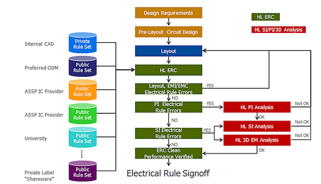
As IC vendors, ODM vendors, and others realize that an encrypted ERC rule set is an elegant way of delivering lightweight analysis engines for performance checking, the number and variety of commercially available rule sets will increase. Vendors, design centers and customer marketing/support teams can use them to ensure that chipset-centric design guidelines are observed during the layout process. This will help make sure that a PCB moves to manufacturing on time and the forecast delivery for IC vendor chipsets is not disrupted.
In cases where certain PCBs within a multi-board system are outsourced to an ODM, ERC rule sets can augment/replace visual inspection methods used during typical incoming inspection and design reviews. The ODMs certainly possess extensive design knowledge for most contracted designs. Each ODM can develop an encrypted ERC rule set to be used as part of standard in-house design practices and it can be passed on to customers to help speed up their incoming inspection and acceptance of the design.
Encrypted HyperLynx ERC rule sets enable universities, consultants, material suppliers and component providers in the PCB design and manufacturing food chain to deliver their own electrical rule IP securely to PCB engineers. This will become increasingly important as PCB speeds increase and thereby require more exhaustive performance verification.
Component manufacturers especially can help their customers ensure proper use of their products by providing rule sets that determine the power delivery/isolation rules or recommended interconnect topologies for critical signals that should followed. The types and varieties of rule sets that improve overall design quality and performance margins are left to the clever minds of the rule set developer.
Figure 4 Pervasive HyperLynx ERC rule sets (Source: Mentor Graphics)
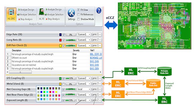
In cases where multiple PCBs are designed across geographically dispersed design teams, you need a work flow where ERC occurs concurrently with layout. Under this model, layout engineers can choose to run multiple rule sets on a network of computers. A concurrent analysis tool manager (Figure 5) enables many different ERC runs based upon multiple rule sets to be assigned to different network servers as layout progresses. As the number of PCBs under design, the number of designers actively performing layout, and design sizes and rule set complexity increase, there will be a growing need to launch multiple rule checks and to manage violation resolution concurrently with the layout.
Figure 5 Multi-user, multi-rule, multi-engine concurrent HyperLynx ERC (Source: Mentor Graphics)
Electrical rule checks help ensure a clean design
The electrical performance of all PCBs comprising an entire system can now be assessed in a timely manner for compliance against original design performance goals. As rule violations are detected, the simulation triage described earlier is applied to ensure only critical errors receive more detailed SI/PI simulations to evaluate whether or not each violation requires repair. Higher quality designs with better design margins that reach production volume sooner are the benefits to those companies that ‘DARE’ to change the way they verify electrical performance.
About the author
Rod Dudzinski is responsible for IE3D market and business development at Mentor Graphics. He has a successful history of leading the development and introduction of new IC place and route, timing/circuit simulation and modeling, and EM Synthesis products into the EDA marketplace. Rod’s experience spans 25 years. Prior to Mentor, Rod held positions at Zeland Software, Lorentz Solution, Cooper & Chyan Technologies and Cadence Design Systems.
Contact
Mentor Graphics
Corporate Office
8005 SW Boeckman Rd
Wilsonville
OR 97070
USA
T: +1 800 547 3000
W: www.mentor.com
