Master parasitic extraction for leading-edge designs
A comprehensive guide to parasitics, how to perform parasitic extraction and the latest technologies available for this critical task.
The miniaturization and increasing complexity of advanced field effect transistor (FET) designs raise critical challenges in signoff physical verification. When performed accurately, parasitic extraction (PEX), one of the essential steps in signoff verification, can ensure signal and power integrity, circuit speed and performance, and optimal overall design performance. In contrast, inadequate parasitic extraction can result in failure to meet performance targets, or even worse, chip failures.
FinFETs and gate-all-around FETs (GAAFETs) are the transistor architectures of choice at advanced nodes. Key extraction challenges in advanced non-planar processes are related to interconnect pitch and minimum dimensions scaling, which, respectively, inherently increase coupling capacitances and parasitic resistances. Other critical challenges in these technologies are the result of the 3D nature of finFETs and GAAFETs, and the small distances between the device and all its local interconnect layers.
Parasitic effects are not intentional—they are an unavoidable byproduct of designing and building electronic devices. Not all parasitics can or need to be eliminated in an IC layout—if their impact on circuit performance is negligible, designers can simply ignore them. However more often, designers must mitigate the impact of parasitics in a circuit using a variety of techniques.
With more densely packed devices and interconnects at advanced nodes, parasitics become more pronounced, error margins shrink, and more accurate PEX is required to ensure optimal circuit performance. This article analyzes key parasitic resistance and capacitance challenges for leading-edge nodes and discuss the PEX techniques needed to ensure accurate extraction.
Parasitics in IC design
Before taking a dive deep into advanced node PEX, let’s discuss parasitic resistance, capacitance, and inductance basics and the unwanted effects they cause in integrated circuit (IC) designs.
What is parasitic capacitance?
Parasitic capacitance is the unintended capacitance that develops between conductors in an electrical circuit. To calculate parasitic capacitance, designers measure the area between the metals, the dielectric constant between them, and the distance between the two metals (Figure 1).
By taking these values into account, EDA extraction tools such as the Calibre xACT tool from Siemens EDA can automatically extract (calculate) the parasitic capacitance and analyze its impact on the circuit’s performance. If it causes the circuit to fail to meet performance targets, the tool flags the parasitic capacitance as an error to be resolved.
Most chips have many layers, making parasitic capacitance calculation more complicated. A PEX tool must calculate the effective capacitance through all these dielectric layers and through non-flat metal plates (Figure 2).
What is parasitic resistance?
Parasitic resistance is the unwanted resistance that occurs when current flows through a metal interconnect that is not intended to act as a resistor. For example, designers always want perfect, non-resistive connections between two devices, but the interconnect material characteristics are never ideal. They add resistance to the current, which can contribute to large delays through the wires, affecting overall performance of the chip or causing certain parts of the chip to work incorrectly.
Resistance can be determined using a relatively simple hand calculation (counting squares) that accounts for the conductor’s length, width, thickness, and resistivity. Thickness and resistivity are normally fixed for each conductor layer, so they can be replaced by a variable called the sheet resistance (RSH), or square resistance. In contrast, the length and width of the conductor vary, resulting in varied resistance values. By knowing the RSH and counting the number of squares within the material in the same direction as the current, engineers can easily determine the resistance of any rectangular wire segment (Figure 3).

Figure 3. Counting squares method of calculating resistance. The resistance is equal to the sheet resistance times the number of squares, which in both cases is three (Siemens EDA – click to enlarge)
What is parasitic inductance?
Electric inductance is a universal property of all conductors, but not all inductance is created equal. When talking about ICs, parasitic inductance describes an unwanted effect that is present in all circuits. This type of inductance is not introduced deliberately, as is the case with intentionally added inductance, but rather is a natural consequence of the laws of physics. A constant current flowing through a conductor produces a constant magnetic field, and a variable magnetic field induces a voltage in all nearby conductors, including the conductor used to create the magnetic field in the first place. These two effects combine to form parasitic inductance.
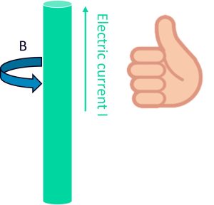
Figure 4. The inductance right hand rule: point your right thumb in the direction of the current and curl your fingers to represent the magnetic field B
Parasitic inductance can produce unwanted effects, especially when designing at high frequencies, or where there are long, fast-switching nets with low resistance such as clocks. Inductance is based on a number of factors. One factor is the distance of the current return path, such as the ground VSS or the power VDD, as inductance is a strong function of this distance. However, the dimensions of the conducting material itself can also play a role in inductance, although to a weaker degree.
To mitigate issues caused by parasitic inductance, designers often try to ensure that there is a nearby ground line to provide a small current loop. But even with these measures in place, inductance effects can be significant.
What is parasitic extraction?
PEX is the identification and measurement of the unintended electrical effects created by a layout’s geometries and materials. PEX enables designers to incorporate these measurements into simulations to predict the circuit’s actual performance. If the design doesn’t meet specifications, designers must adjust the layout to minimize the parasitic impacts. If PEX is not performed accurately and thoroughly, parasitics can cause defects, including chip failures. In contrast, accurate PEX can help design teams ensure signal and power integrity, circuit speed, and optimal overall design performance.
Designers use EDA PEX tools such as the Calibre xACT, Calibre xACT 3D, and Calibre xL tools to automatically measure parasitic capacitance, resistance, and inductance in a layout. The Calibre xACT and Calibre xACT 3D tools provide rule-based and field solver parasitic resistance and capacitance extraction, while the Calibre xL tool provides parasitic inductance extraction. Together, the Calibre PEX toolsuite provides the broad range of PEX techniques needed to accurately calculate parasitics in today’s complex leading-edge IC designs.
Parasitic extraction in advanced node designs
Signal integrity
Parasitic resistance, capacitance, and inductance are key elements that can impact signal quality when designing integrated circuits at advanced nodes such as 3nm. Parasitic resistance can lead to voltage drops and affect timing, while parasitic capacitance can create signal noise and low-frequency oscillations that compromise signal fidelity. Similarly, parasitic inductance can induce voltage spikes and ringing that distort signals. Managing these parasitic elements is crucial to ensure reliable data transmission in advanced integrated circuits. After taking these parasitics into consideration in simulation, if the circuit no longer meets specifications, then the layout engineer must reduce the parasitics, such as by widening the wires to reduce parasitic resistance, moving wires away from each other when there is too much coupling capacitance, and putting ground return paths near signal nets to reduce inductance.
Power integrity
Parasitic capacitance and resistance can significantly impact power integrity. These parasitics can cause voltage fluctuations when large currents flow through the circuit and can result in power integrity issues such as voltage (IR) drop. To address these issues, designers use static and dynamic IR drop analysis to identify problematic areas and devise solutions to improve power distribution. Techniques to reduce IR drop include designing wider power planes and using more power pins for better distribution. Ensuring good power integrity is essential for optimal circuit performance and reliable operation.
Electromigration
Electromigration (EM) is the migration of metal atoms in a conductor caused by the flow of electrons (Figure 5). As the atoms move, they create voids and hillocks, which can eventually lead to a fault in the device. High current density is one of the key factors leading to EM. When too much current moves through a narrow passage with high resistance, EM occurs. Over time, EM causes chip failures by creating hillocks, which cause a short to the neighboring wire, or voids, which cause an open in the circuit.
Accurate measurement of parasitic resistance is essential to obtaining an accurate current density. If there are current density violations, designers must widen the wires to reduce the current density until that segment no longer violates current density rules.
FinFET and GAAFET architectures
Metal-oxide-semiconductor field-effect transistors (MOSFETs) with a planar gate topology effectively controlled FET channels down to approximately 25nm channel length [10]. However, as transistors continued to scale downwards, short channel effects (SCEs) started to significantly weaken the planar gate control over the channel. These SCEs are undesirable changes in short-channel FET behavior that result in increased leakage currents with further gate length (Lg) scaling in each generation.
Transistor architectures currently used in advanced process nodes include finFETs and GAAFETs. Critical parasitics challenges of these architectures are related to the 3D nature of finFETs and GAAFETs, and the small distances between the device and all its local interconnect layers.
FinFETs
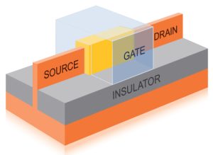
FinFETs have a double or triple gate that wraps around a vertical channel resembling a fin (Figure 6). FinFETS offer strong channel control at small channel lengths, but they still suffer from SCEs at extremely scaled process features like tiny gate lengths or very tall fin profiles.
GAAFETs
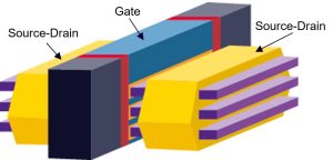
Rather than attempting to further scale finFET processes, the semiconductor industry adopted nanosheet GAAFET architectures. Nanosheet GAAFETs have vertically stacked horizontal channels that allow for larger effective channel widths than finFETs without any increase in the 2D footprint (Figure 7). The ability to add nanosheets vertically to achieve larger effective channel widths with GAAFETs allows designers to place ‘wider’ transistors that drive larger currents without expanding 2D space, increasing transistor density. GAAFET gates also fully wrap around the channels, allowing for superior control over SCEs compared to finFET tri-gates. This new architecture is already in production in 3 nm nodes.
These devices have an infinite number of possible FET cell configurations with slightly varying source/drain and gate-via locations. Vias can be placed on the source and drain, on the active gates, or on the gate material outside the active gate area. Each via placement and geometry variation can significantly affect the coupling capacitance effects on the 3D transistor. Rule-based tools using pattern matching cannot capture all the possible via placement variations in 3D devices with multiple complex geometries in close proximity to each other. To accurately extract parasitic capacitance interactions around finFET and GAAFET transistors, a field solver is required . Field solvers are geometry-agnostic, enabling them to perform accurate PEX around finFET and GAAFET devices regardless of the layout.
However, because field solvers directly solve the electric fields from the geometries instead of using rule-based equations, they can require longer runtimes. To enable design teams to manage PEX runtimes, the Calibre xACT tool contains a hybrid-engine parasitic resistance and capacitance extractor that uses both its fast, rule-based engine for back-end-of-line (BEOL) layers, and its deterministic, mesh-based 3D field-solver to calculate the parasitic capacitances in the front-end-of-line (FEOL) and middle-of-line (MOL). Designers may also use the field solver on certain critical routing nets using the ‘xACT 3D Select’ extraction mode (Figure 8).
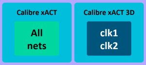
Figure 8. The Calibre xACT tool can call the Calibre xACT 3D field solver for extraction of specified nets only (Siemens EDA)
Multi-corner extraction
Geometries drawn in layouts differ from the actual geometries patterned during fabrication due to systematic, multi-patterning, and random process variations. Modeling these variations is required in advanced extraction flows because interconnect and dielectric geometry variations can significantly influence parasitic capacitances and resistances. For example, if two metal lines turn out to be narrower than expected, they will suffer from greater than expected parasitic resistance. In the case of double-patterning mask shifts, metal lines can be placed closer or further apart than expected, changing their coupling capacitance. These variations can make a significant difference in advanced nodes. Advanced PEX tools must account for these deviations, as well as other factors like temperature variations.
To account for the issues that come with process, multi-patterning, and temperature variations, designers use a statistical approach that includes nominal-, best-, and worst-case corner scenarios. For example, the worst corner scenario in a specific node or design type can include the worst and least likely coupling capacitance corners, in which double-patterning masks are significantly misaligned. A PEX run including models of these scenarios yields different results than the nominal scenario. If the design passes all corner cases in post-extraction simulation, it will be a good indicator that it will work as expected.
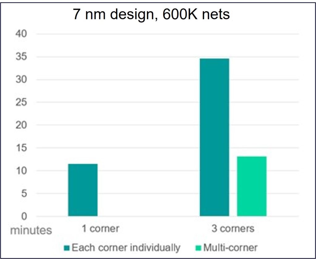
Both the Calibre xACT and Calibre xACT 3D tools offer a multi-corner extraction solution that efficiently addresses process and temperature corner scenarios by extracting best, nominal, and worst corner cases simultaneously in a single run. The necessary process corners are included in foundry-qualified Calibre decks. This accelerated multi-corner extraction approach allows design teams to verify their design with parasitics still satisfies performance requirements in all included corner scenarios.
Figure 9 highlights the performance advantages of using Calibre xACT multi-corner extraction versus single corner extraction – there is less than a 10% runtime increase per corner compared to the 100% runtime increase per corner using sequential single-corner runs.
Modeling metal fill parasitics
Accounting for metal fill parasitic effects on signal nets is important, but often challenging for designs in progress. Designers may want to perform extraction on a portion of the design to verify a design block will work as expected, but the outside region of the design block is empty because fill has not yet been placed. With the Calibre PEX tools, they can enable a metal fill density modeling option for the extraction run. Extracting the design block with this setting enabled ensures the parasitic output values include the modeled fill effects.
The foundry-qualified Calibre decks include statements that control whether floating nets (i.e., metal fill) should be treated as floating or grounded when calculating their effects on signal nets, and whether those floating nets should be included in the netlist (Figure 10).
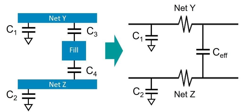
Figure 10. Left: Fill is treated as floating and its coupling capacitances to signal nets are denoted. Right: Fill net is eliminated (not included in the netlist), and an equivalent Ceff coupling capacitance between signal nets is applied to account for the fill parasitic effects on the signal nets
Netlist reduction
Output netlist sizes can be large, especially at advanced process nodes. If the netlist is too large, it cannot be simulated. The Calibre xACT and Calibre xACT 3D tools support multiple parasitic reduction strategies for different design types and constraints. The foundry-qualified deck includes pre-defined reduction recipes, but designers can also include or exclude customized parasitic reduction techniques to control the netlist size as desired. The goal of netlist reduction is to find an appropriate tradeoff between netlist size and post-extraction simulation performance.
The pre-defined coupled capacitance reduction technique combines and grounds coupled capacitances (CCs) when the total CC between any pair of nets falls below a user-specified threshold. This threshold can be an absolute value, or a ratio relative to the intrinsic capacitance to the signal net. Figure 11 illustrates the elimination of a coupling capacitor and updated intrinsic (capacitance to ground) values.

Figure 11. CC reduction: CC is eliminated because it falls below the capacitance threshold value specified. The intrinsic signal net capacitances are updated to account for the eliminated coupled capacitor
Another important reduction technique included in advanced process node rule decks is time constant equilibration reduction (TICER). TICER instructs the Calibre xACT tool to shorten the output netlist size while preserving the circuit’s frequency response from DC up to a specified frequency parameter (Figure 12).
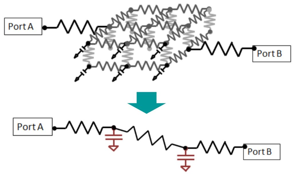
Figure 12. A 3×3 via connection is reduced while maintaining the required circuit frequency response
Summary
Designing integrated circuits for leading-edge process technology nodes is a challenging task that requires advanced tools and techniques to balance accuracy and productivity. When designing circuits at advanced non-planar technology nodes, managing parasitic capacitance, resistance, and inductance is a critical success factor. It is essential to be aware of the factors that cause parasitic resistance, capacitance, and inductance, and how to minimize them effectively. Keeping parasitics under control in advanced node designs requires multiple extraction techniques to ensure accurate and complete parasitics analysis. The comprehensive circuit analysis capabilities of the Calibre extraction tools enable designers to achieve accurate and efficient modeling of advanced node design parasitics in advanced node designs.
Further reading
For more in-depth information about parasitics in leading-edge nodes and the advanced capabilities of the Calibre PEX toolsuite, read the Siemens EDA technical paper, Efficient and accurate parasitic extraction for leading-edge process node IC designs.
About the authors
Dilan Heredia is a field application engineer for Calibre Design Solutions at Siemens EDA. He supports various technologies within the Calibre nmPlatform toolsuite, with a focus on DRC, LVS, and parasitic extraction. Dilan holds a Bachelor of Science degree in electrical engineering from the University of Nevada, Las Vegas, specializing in mixed-signal IC design disciplines. He can be reached at dilanDOTheredia@siemensDOTcom
Karen Chow is a principal product engineer for the Calibre Design Solutions group in Siemens Digital Industries Software, focusing on driving parasitic extraction development in analog and RF design flows. Prior to joining Siemens, Karen worked in the telecommunications and EDA industries, designing analog ICs, and supporting EDA tool development. She received her Bachelor of Science degree in electrical engineering from the University of Calgary, and her MBA from Marylhurst University. Karen can be reached at karenDOTchow@siemensDOTcom.


