Simulation predicts performance of automotive Ethernet
Ethernet is set to become one of the key communications standards for automotive. Early system-level simulation lets designers gauge performance before moving to hardware prototypes.
Ethernet has already become a useful communication mechanism for in-car systems, used primarily for onboard diagnostics and firmware downloads because it offers much higher bandwidth than the Controller Area Network (CAN). Ethernet now has the potential to interconnect many other subsystems within the car.
The automotive environment places a number of restrictions on digital communications that standard Ethernet cannot easily satisfy. A key requirement is that, although higher datarates than are readily available with CAN, FlexRay, or MOST are desirable that cannot come at the cost of higher cable cost or, more importantly, weight. However, standard Ethernet requires two pairs of conductors for full-duplex operation, increasing overall cable weight.
Single-pair Ethernet
The BroadR-Reach physical-layer transceiver specification created by Broadcom and accepted by a wide range of automotive companies and component suppliers through the One-Pair Ethernet (OPEN) Alliance uses techniques such as echo cancellation to enable full-duplex operation over a single unshielded twisted pair (UTP) up to 15m in length. This is shorter than standard Ethernet but is adequate for vehicular use and provides for changes to the signal transmission characteristics to improve automotive compatibility.
In addition to echo cancellation, the BroadR-Reach standard adopts pulse amplitude modulation 3 (PAM3) to help minimize bandwidth such that communication operates over a bandwidth range – 33.3MHz – that suits UTP cable best as well as helping to achieve compliance with the electromagnetic interference (EMI) restrictions of the automotive environment and provide high noise immunity. Further power spectral density shaping for the transmitter is intended to ensure the signal falls within automotive electromagnetic emission masks.
Despite these changes, BroadR-Reach maintains compatibility with the standard Ethernet MAC layer and the Media Independent Interface (MII). However, the changes required by the PHY introduce a number of signal-integrity challenges during system development and integration, especially when trying to design to stringent cost and reliability targets.
Performance prediction
There are a number of variables involved in design for automotive Ethernet that can render the final system unable to meet performance targets such as jitter and EMI. As well as the PHY silicon itself, connectors, cables and overall layout will affect system performance. It is an expensive process to physically verify system behavior and make a series of changes to ensure the design passes key tests for jitter, droop and power spectral density.
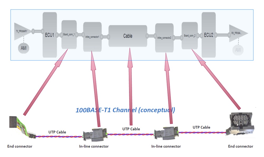
Image Mapping between physical elements and their SystemSI models
A virtual model provides the ability to predict system performance before moving to hardware prototypes. Designers can use the model to estimate how well the design will cope with different PCB stack-ups, potentially using lower-cost assemblies, and different lengths and arrangements of UTP and inline connectors that are used to interconnect lengths of cable.
The virtual reference design platform available for the automotive Ethernet PHY intellectual-property (IP) cores from Cadence Design Systems is designed to ease the task of building a virtual model for experimentation and performance prediction. Through a combination of Sigrity SystemSI and MatLab from The Mathworks, the virtual reference design platform can analyze performance and determine the likelihood of the actual hardware passing the key compliance tests, such as conformance to the power spectral density masks for EMI performance.
The virtual reference design platform enables simulation of the PHY in the context of PCBs used for electronic control units (ECU), connectors and cable. To perform system-level simulation, the cable topologies are captured in SystemSI with S-parameter blocks that estimate their behavior mapped to portions of the link, such as the end connectors on the ECU boards or the inline connectors that join lengths of UTP cable. Cable models can be switched in and out to create variants in the SystemSI environment.
Virtual compliance tests
Using SystemSI, simulations can be to allow overall parameters to be extracted, including insertion loss, return loss and mode conversion loss. Impulse response can be shown as well, to estimate the required equalization needed in the PHY control.
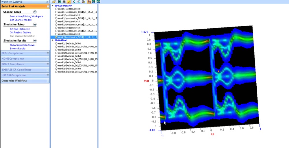
Image Simulated eye diagram of PAM3 signal for automotive Ethernet
The SystemSI simulator can run numerous data cycles. By running the simulation for 50,000 bits or more, it is possible to build eye diagrams analogous to those captured by conventional hardware test equipment, making it possible to gauge bitrate error performance and jitter. To verify TX compliance, the model allows the channel to be shorted by clicking on links to alter the cable configuration.
Models constructed in Ibis AMI cater for the various performance tests, such as jitter, droop and power spectral density, needed to check for compliance to the standard. The waveforms generated by the models can then be passed to Matlab to determine whether the tests would pass or fail.
Through a combination of modelling and simulation tools, designers can more easily and realistically gauge the performance of a silicon and PCB combination under the stringent conditions required for automotive Ethernet.