Standard cell IP must pass the litho-friendly routing test
Standard cell intellectual property blocks (IP) are the building blocks of digital design, implementing the logic cells known as gates. Examples include buffers, invertors, AND gates, OR gates, D flip flops, D latches, etc. A system-on-chip (SoC) or block physical implementation team normally does not have its own standard cells. Instead, its designers use IP libraries that have either been developed by an internal standard cell design team or purchased from specialty IP vendors. An IP library typically contains 300 to 800 standard cells. Once these standard cells are designed and verified, they are assumed to be production-ready.
It is crucial that when these standard cells are assembled into a larger design by SoC tools, the resulting design is “correct by construction,” meaning it passes all design rule checks (DRC-clean), layout vs schematic comparisons (LVS-clean), timing requirements, and design for manufacturing checks (DFM-clean). To achieve that goal, a lot of resources are dedicated to a standard cell’s verification prior to its release. The typical standard cell verification includes the following phases:
- Cell characterization—functionality, timing, and power
- Cell verification—DRC, LVS, electrical rule checking (ERC)
- DFM compliance—litho-friendly design (LFD) simulation
- Cell view creation—timing library, SPICE library, GDS library, place and route (P&R) phantom library
The problem
Most of these verification steps are well-established, and can be performed on each cell either in standalone mode or within some simple context. However, DFM verification is a relatively new requirement for IP. Its adoption only started to become common at the 28nm node, and it is still being refined for standard cell compliance.
For lithography verification, it is extremely important to consider the neighboring geometric context.
Quality assurance (QA) teams have only partially addressed the lithographic challenge by incorporating the placement of neighboring cells when performing LFD verification on standard cells. However, placement context alone is insufficient to ensure lithographic compliance.
Recently, we worked with an SoC implementation team whose design was being flagged with hundreds of lithographic hotspots. Upon detailed investigation, the team was able to correlate the majority to a handful of standard cells used hundreds of times in the design. By themselves, the cells did not contain any lithographic hotspots, and even after placement, there were no hotspots. It turned out that the lithographic hotspots were being created during routing.
As this example shows, it is critical to ensure that standard cells are litho-friendly in relation to the routing tool being used.
So, what can be done to prevent these types of design roadblocks.
Typically, after a design is synthesized to a gate-level netlist (by a logic design team), it is handed off to the SoC or digital block physical implementation team. Figure 1 lists the steps the SoC team performs.
Figure 1 SoC design implementation steps (Source: Mentor Graphics)
Because lithographic verification occurs towards the end of the block/SoC physical implementation, finding and fixing lithographic hotspots at this stage has a major impact on tape-out schedules.
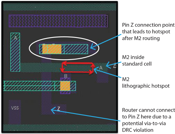
Figure 2 shows an original standard cell layout after routing. Within the cell is an A pin running horizontally on M2. On the track above and below the A pin are two M1 pins that must be connected. The router created horizontal M2 wires to both of these pins. The particular combination of these three M2 horizontal lines with their specific run lengths and end point locations creates a lithographic hotspot on pin A. In this example, the router could not have routed this cell differently.
Figure 2 Litho-unfriendly standard cell layout after routing (Source: Mentor Graphics)
At this point, there are two ways to resolve the issue.
The design team can redo the design and exclude the problematic standard cells. This option requires the team to go all the way back to the synthesis step. For an average block size of 5×5 sq mm, this would probably delay tapeout by a month at least. Obviously, this is not very appealing to teams reaching the final stage of a design delivery schedule.
Alternatively, the team can redesign the bad cell. What that really means is they can contact the standard cell design team or the company they purchased the standard cell IP from, and ask them to redesign the cell.
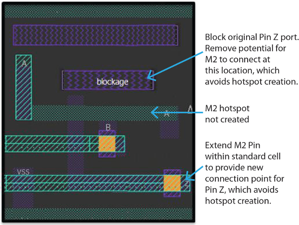
Figure 3 illustrates one way the previous problematic standard cell might be redesigned. Once a new cell is available, the team must replace the bad cells in the layout and reroute the design. If the team is lucky, it will be able to keep the original floorplan and placement, but that is not always possible. Rerouting can be difficult if the design is congested, and it also requires the team to re-run the timing closure. Getting a redesigned cell—maybe a week, if you’re lucky. If we stick with the 5×5 sq mm block size, rerouting with timing closure will take about two weeks. In all, 2-3 weeks at a minimum, and not much better than the first option.
Figure 3 Redesigned cell to avoid litho hotspots (Source: Mentor Graphics)
The solution
To prevent such costly delays, standard cell design teams should incorporate lithographic-friendly routability testing into development and QA processes prior to release. By running a lithography check on these standard cells in a routing environment, the standard cell design team can determine if the routing options for that cell are too limited to ensure manufacturability when placed in a block later on. If so, they can redesign the cell to remove these limitations before adding it to a library and releasing it to the chip design teams or placing it on the market.
About the author
Joe Kwan is the Product Marketing Manager for Calibre LFD and Calibre DFM Services at Mentor Graphics. He previously worked at VLSI Technology, COMPASS Design Automation, and Virtual Silicon. Joe received a BA in Computer Science from the University of California, Berkeley, and an MS in Electrical Engineering from Stanford University.


