Manufacturing a profit
DFM is essential to differentiating your products in the market, says Luigi Capodieci
The beginnings of DFM
Traditional design rules are sets of geometrical constraints defining both the size and spacing of design features, predicated on linear measurements with a fixed threshold, such as the minimum distance between adjacent interconnect wires. The ‘workhorse’ of verification, design rules are used to ensure the physical and electrical manufacturability of design layouts. However, manufacturability began to erode when integration technologies entered the ‘subresolution era’ from 65nm. Design rule compliance no longer guaranteed that layouts could be turned into chips.
In the transition from 65nm to 45nm, as the size of features and the spaces between them decreased, many physical process factors that were relatively insignificant at earlier nodes began to impact yield and performance (Figure 1). Non-linear effects due to systematic process variation had to be mapped onto interactions between features, making design rule values dependent on multi-parameter constraints. This resulted in design components that could not be created in ways that complied with all of both the design rule criteria and the other design specifications.
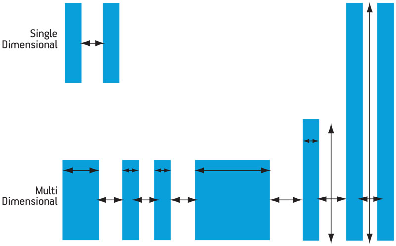
Figure 1
Increasing interdependent interactions between multiple features
The response to these challenges started with the design rules as the most readily available tools. In an attempt to control these interactions and dependencies, the rules for advanced nodes became both more numerous and more complex. They often encompassed multiple operations per rule, such as multi-variable equations that expressed complex spatial constraints and relationships between design features within a certain 2D proximity. As these rules became more numerous and more complex with each node (Figure 2), the computational complexity of design rule checks (DRCs) and the number of potential violations grew exponentially.
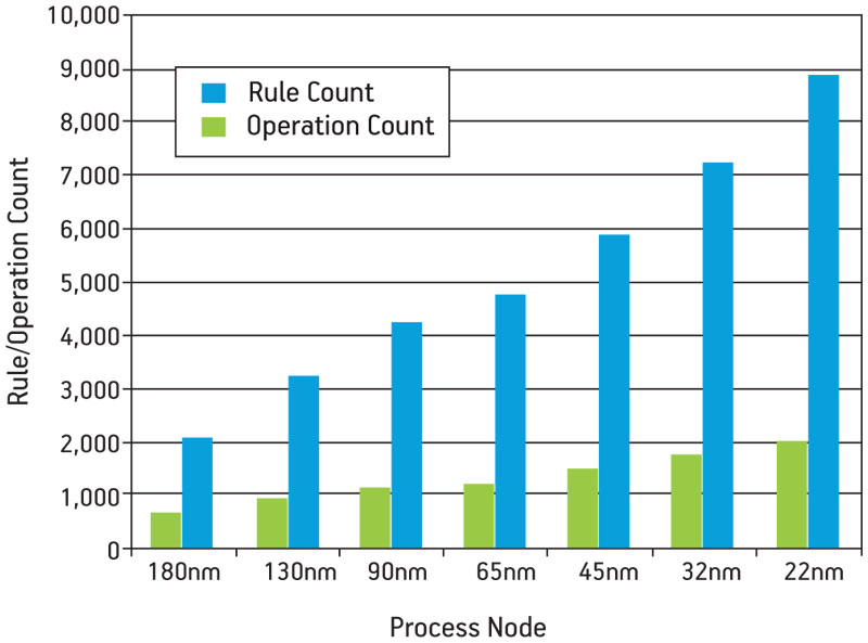
Figure 2
Increase in design rules and operations per process node
More new techniques and tools were needed to ensure timely, profitable production at advanced nodes. The notion of anticipating and ‘designing out’ known construction and production issues before a design reached manufacturing evolved into design for manufacturing (DFM), a proactive approach to advanced node production and performance challenges.
DFM analysis and verification
The first DFM applications addressed yield issues caused by random defects and catastrophic failures. These process-based (or physical) DFM solutions identified and corrected design areas that were vulnerable to functional failures, such as shorts and opens. Wire spreading, via doubling and critical area analysis became mainstream.
The next generation of DFM solutions began addressing parametric yield loss caused by manufacturing variation affecting power, timing, or other performance specifications. These included the device or interconnect parameters that are affected by process variability and can adversely impact chip performance. Lithography and chemical-mechanical polishing (CMP) modeling, combined with device characterization and timing analysis, captured the effects of process variations on chip performance. Optical proximity correction (OPC) tools adjusted the manufacturing process itself to implement the optimized solution proposed by a DFM tool.
At GlobalFoundries, we use a wide range of these DFM capabilities, techniques and tools to manage the progression of complexity and interaction in advanced node designs.
Rule-based DFM
The purpose of design rules is to provide a level of abstraction that allows designers to implement compliant configurations with the assurance that the features can be manufactured and the circuit will work. Even complex issues in resolution enhancement technology (RET)—such as dielectric constant (k), numerical aperture (NA), source frequency (λ), source shape and off-axis illumination—are summarized in the form of allowable geometric measurements such as minimum line width, minimum space, and forbidden pitches. Complex interactions, such as those between aerial image, photoresist and line-ends, can be defined as specifications on tip-to-tip spacing and tip-to-line spacing using DRC. As we develop design rule decks, we do so with the goal of minimizing manufacturing failures and maximizing performance and yield. But as discussed above, design rules are not enough for the challenges encountered at 65nm and below.
In addition to the required deck, we also provide recommended rules, developed to address specific problem constructions and features. Recommended rules suggest (but do not require) a wide variety of design constraints that improve the design’s ability to withstand manufacturing process variation. Their purpose is to generally define ranges of acceptable tolerances and interacting variables, thereby reducing the number of manufacturing failures caused by systematic variation.
Our experience demonstrates that designers who apply recommended rules during physical verification can further enhance a design’s resistance to process variation.
DRC Plus
At GlobalFoundries, we quickly recognized the limitations of traditional design rules at advanced nodes. Even the use of recommended rules still allows the creation of geometries that, while DRC-clean, are not manufacturable. In fact, forcing a geometry into compliance with one rule often leads to the creation of an equally intractable geometry that violates another rule.
With that in mind, we augmented our design rule decks with DRC Plus, a process that adds fast 2D pattern matching to standard DRC to identify problematic 2D configurations. DRC Plus offers the same pass/fail criteria as a standard design rule, while providing the means to quickly identify and mark undesirable 2D geometries, and suggest the desired fix (Figure 3, p.9).
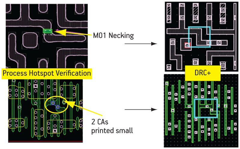
Figure 3
DRC Plus offers fast 2D pattern matching to find and fix problem configurations
Model-based DFM
Model-based DFM tools use process simulations to predict manufacturing results, allowing engineers to refine and correct layouts before sending their designs to the foundry. For example, lithographic simulation identifies specific design features most likely to suffer distortion during the actual process.
To enable precise lithographic modeling, GlobalFoundries provides designers with a litho-friendly design (LFD) kit for the process, much as it would a DRC kit. The designer can then run lithography simulations and get an accurate description of how a layout will perform under our specific process. Hotspots can then be revised before tapeout. Figure 4 shows examples of the results obtained from LFD simulation.
Figure 4
Lithographic process hotspot verification based on a state-of-the-art lithography simulation engine
The goal is to drive the design to a sign-off that is both LFD and DRC-clean. With lithography simulation, designers can create designs and check them with our foundry- and process-specific LFD verification tools to ensure they are free of lithographic hotspots before they are submitted for fabrication. If lithographic simulation is run in conjunction with the place and route (P&R) process, design teams can avoid creating problematic layouts or features, reducing the risks of both expensive respins and lithographic failures.
Likewise, modeling the chemical-mechanical polishing process can predict the final planarity of a wafer. Variations in thickness created during CMP can lead to manufacturing and parametric performance issues. Adding metal fill (non-functional metal shapes) to ‘white space’ regions in a design helps achieve an even distribution of metal across the die, reducing the bridging attributable to dishing and thickness variations. By achieving a more uniform thickness, designers can reduce variations in
interconnect resistance. However, adding too much fill can increase parasitic capacitance.
The goal of any fill process is to add the minimum amount of fill in the right places and in the right shapes so that you optimize performance while minimizing manufacturing variations. Early attempts to manage metal fill used design rules that defined allowable metal density based primarily on three criteria: the foundry’s minimum and maximum density percentages; the allowable gradient of density variation across a design; and the density magnitude (difference between minimum and maximum densities over the whole die). These techniques have some value but still fall far short of simulating the actual manufacturing process on a specific design.
Using a CMP simulation based on the actual manufacturing process enables designers to add as few fill shapes as possible while still achieving specific planarity goals. This will deliver the most specific and customized design possible for a given manufacturing process.
Variability based DFM
Due to pattern fidelity issues at advanced nodes, there is a delta between the silicon shape and drawn layout. This variation can reduce performance or create catastrophic manufacturing failures. Designers must be able to extract this delta and bring it into the design flow for analysis, control and minimization. Otherwise, the trend toward poorly matching silicon behavior for transistors (for both Ion and Ioff) and interconnect layers will continue to grow.
Contour-based extraction using lithography simulation is one example of variability based DFM. Silicon contours or shapes are predicted from a layout so that realistic process-based patterning can be used directly at an early stage in the design flow. Contour-based extraction uses simulated critical dimensions (CD) for transistor gates (more accurate than traditional ‘drawn’ CD) to extract timing information and characterize speed-paths for a design. With an accurate model of the current density through the device width, and detailed knowledge of the device shape, it is possible to predict currents for 2D transistor shapes with accurate comparison to silicon measurements (Figure 5).
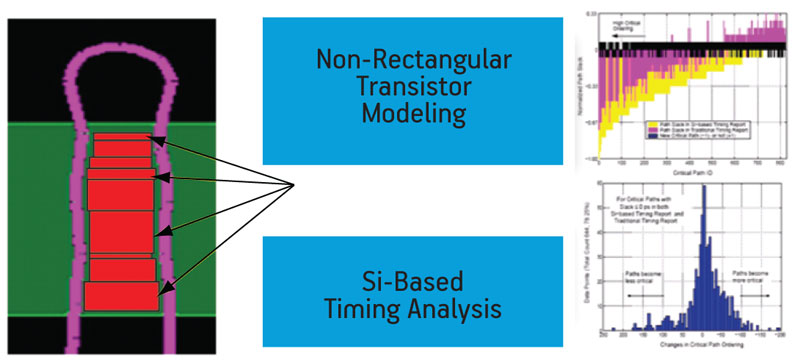
Figure 5
Contour-based extraction can be used to predict timing performance
Pushing DFM up the design flow
DFM techniques give designers automated ways of identifying problematic geometries, realistic simulations of manufacturing results, and quantitative manufacturability indices to enable relative yield forecasts prior to production. It follows then that pushing DFM usage upstream in the design flow will lead to fewer structural and systematic yield-limiting layout configurations reaching the foundry.
Double patterning is one technology being used to offset the RET issues encountered at the most advanced nodes. The challenge here lies is identifying two things:
- Patternability. A set of rules that tell you whether or not a layout can be safely decomposed in isolation.
- Composability. A set of P&R rules or algorithms that guarantee that the complete layout remains decomposable.
Patternability applies during layout construction, such as standard cell design and routing style definition. It is a relatively easy challenge to address, and can generally be taken care of by the P&R tools once rules have been established because it focuses on intrinsic effects that are local in nature.
By contrast, composability issues require that layout designers recognize that new configurations can be created by placing structures next to each other. For example, during standard cell placement, multiple intellectual property (IP) blocks are often
integrated to form a design. Each layout block can be double-patterning compliant in isolation, but when placed next to another block, the combination may create structures that cannot be adequately decomposed for a double-patterning process.
The traditional approach to double patterning is to determine only if structures are patternable. Composability is not addressed during layout, as everything is checked after placement is complete. Obviously, if the layout construction fails, placement must be repeated until double-patterning compliance is reached.
A proactive DFM approach determines composability and enforces it during P&R. This requires the foundries and EDA vendors to collaborate to create and implement the necessary composability algorithms. Design teams can then enforce double-patterning compliance and eliminate unnecessary repetition of the layout and placement processes.
DFM techniques have to date been employed primarily during verification. Enabling DFM analysis during P&R can prevent surprises late in the design and verification cycle, and reduce the number of both DRC runs and lengthy debugging cycles. A litho-aware router can perform the lithographic simulation and hotspot analysis discussed earlier, and helps you to avoid creating structures that become hotpots. All of the DFM techniques that have been discussed in this article can be applied during P&R to provide the earliest detection and repair of DRC/DFM rule violations, and problematic constructions as well as geometries. They can also be used to apply the automated optimization techniques that implement yield improvement modifications.
DFM has enabled production of designs to continue through the most advanced nodes. To ensure its ongoing effectiveness, DFM should be incorporated into the earliest stages of design and verification. Bringing this family of signoff analysis and automated correction and improvement techniques into the design process not only shortens the time needed to achieve manufacturing closure, but also ensures that performance and profitability targets can be realized.
Luigi Capodieci is an R&D fellow and DFM director at GlobalFoundries (www.globalfoundries.com).