How automated power/ground short checks slash time during implementation
Early detection using design integrity checks during implementation from abstract LEF/DEF inputs can deliver major efficiencies.
During a system-on-chip (SoC) implementation, multiple design elements, such as intellectual property (IP) blocks, are moving forward at the same time. To enable simultaneous development, the SoC floorplan uses a abstract representation of each block in a library exchange format (LEF) as a placeholder. The SoC integrator inserts the abstracted LEF macros into the floorplan, then merges and validates the physical IP data in a chip-level context using physical verification flows, such as design rule checking (DRC) and layout vs. schematic (LVS). These verification flows remove the data abstraction and apply manufacturability and circuit construction checks to the full hierarchical database to identify any errors that were masked by the use of abstract data.
The block owner is typically responsible for ensuring the abstract provided to the SoC integrator for insertion accurately represents the physical IP. If the IP block design is already complete, the LEF macro should match, in which case there should be no errors. However, in parallelized implementation flows, it can be that the LEF macros that do not match the final IP data because of design changes, user mistakes, or out-of-sync data. The abstract size, pin locations, or boundary size may be different, depending on multiple factors.
Errors found during the early stages of physical design implementation may require a change or changes at the macro level, chip level, or both. Unfortunately, data mismatches between the abstract macro and physical IP blocks can generate significantly high error counts that may disguise the root cause of these errors. This can involve a time-consuming effort to track down and fix.
One such example is when an IP block is larger than the abstract footprint used for that block in the SoC floorplan. This mismatch creates many shorts, all due to that single mistake. Because systemic issues like these are not typically reported by place and route (P&R) floorplanning tools, finding and fixing these conditions before performing design data merging, full-chip physical verification and error debug both reduces total physical verification iteration time, and allows SoC integrators to focus time and effort on resolving the remaining errors.
One means of unmasking these types of error is to apply ‘design integrity’ checks to the abstract data during design implementation, enabling design teams to identify systemic design issues whose root cause creates many violations across a chip, block, or large area, and can be attributed to a single (or multiple related) violations. Let’s take a look at how that might be done.
Power/ground short checking
As mentioned, power/ground shorts are a common source of systemic design issues. Power to ground short checking of a complete hierarchical database with all the physical data is usually performed using an LVS tool. The comprehensive short checking available in LVS tools requires a post-IP-merge GDS or OASIS design database, and a rule deck that includes mapping for all the physical geometries in the design database, layer connectivity definitions, and checks. While this level of LVS short checking will always be much more accurate than running on abstract data, it does not work for a design integrity checking flow, because it happens after the SoC design is merged with the IP blocks. If any shorts are found, they must be fixed and the data re-merge. This adds additional overhead and time to the flow.
In contrast, a power/ground short design integrity check can be applied during design implementation, using the same design exchange format (DEF) and LEF data used in the P&R process. SoC design data can be exported from P&R tools as a DEF database file. Macro placements in the SoC design are typically available as LEF libraries of macros, or individual block macros, from the teams working on a given part of the design. Together, these LEF/DEF data files define the abstract macros, pins, vias, routing, and other objects (such as fill) in the original P&R design. Route shapes obtained from the DEF data include properties defining them as different types—for example, power or ground. Objects defined as a power type that then touch a ground type obviously create a power/ground short. Additional objects, such as via, pin, or fill, can create a bridge short between power and ground types.
However, assembling, converting and analyzing all this information manually would be both impractical and time-consuming. Fortunately, automated design integrity checking can simplify and speed up the process.
Automated short checking
Using the Calibre platform, designers can translate LEF/DEF data into the Calibre-native binary format (GDS/OASIS) by mapping power/ground net data into separate layers. They can then generate a rule deck to automate checking for direct and indirect (bridging through pin, via or fill geometries) interactions between power and ground nets.
The Calibre platform contains foreign database interface (FDI) utilities that translate LEF/DEF databases to either GDSII (fdi2gds) or OASIS (fdi2oasis) format. These FDI utilities accept a layer mapping file that maps LEF/DEF data (vias, nets, pins, etc.) into user-specified layers in the output. Alternatively, these utilities can analyze the specified LEF/DEF data and automatically generate the layer map file, using default hard-coded mapping for LEF/DEF objects.
Figure 1 illustrates this automated flow for power/ground checking, beginning with the LEF/DEF databases. The FDI utilities generate the generic mapping for LEF/DEF objects, update that mapping to achieve the desired data separation in binary output (e.g., mapping the data into separate layers to achieve more granularity for power/ground nets), then uses that mapping information to generate the checks.
Default mapping of DEF objects
The Calibre fdi2gds and fdi2oasis utilities run as command line applications. By enabling map-only mode, designers force the utility to generate the default mapping file without incurring time and resources generating actual binary (GDS/OASIS) output that is not needed.
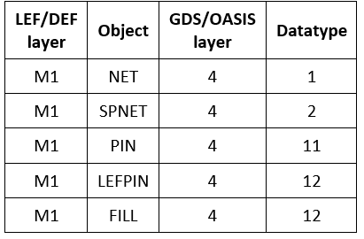
The generated FDI LEF/DEF map file format maps LEF/DEF layer name objects to GDS/OASIS layer number and datatypes. As shown in Table 1, there is no separate mapping of power/ground net data, eliminating the possibility of detecting whether the data sets of the power and ground nets are intersecting with each other or not. There are certain types of nets (power, ground, clock, etc.) that must comply with special rules in the P&R environment, separate from regular nets (signal, IO, etc.) that have their own rules. By default, the FDI utilities map all of this M1 layer special net data (SPNET) to GDS/OASIS layer 4 datatype 2.
Retrieval of power/ground net data from DEF
Designers need a way to separate the power and ground data, so they can check to determine whether or not the nets are interacting with each other to create a short. Using three steps, designers can retrieve just the power and ground net names from a DEF database:
- Modify the provided script to query the DEF database,
- Locate the SPECIALNETS section,
- Capture the net names from any net definitions containing the “USE POWER” or “USE GROUND” specification.
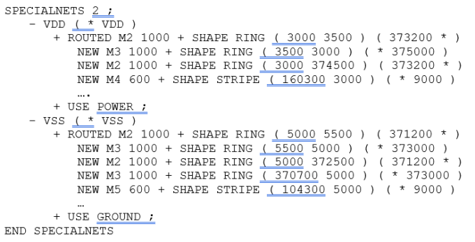
The following code is an example of a SPECIALNETS section in a DEF database that contains two nets: VDD and VSS. Net VDD is a power net, identified by the USE POWER statement, while VSS is defined as a ground net by the USE GROUND statement.
Binary output generation with power/ground net data mapped to separate layers
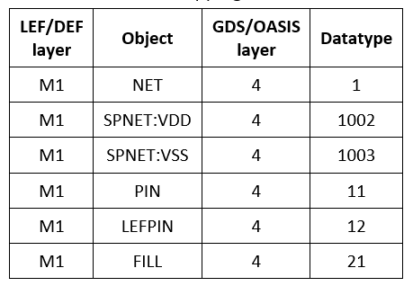
Using the special net names retrieved from the DEF database, the FDI utility generates a new map file that replaces the default mapping with the more granular name-based mapping lines, mapping the special nets into separate layers. This FDI map file modification enables discrete mapping of the M1 DEF power (VDD) and ground (VSS) nets, as shown in Table 2.
Running the FDI utilities with this updated map file produces the binary output with power/ ground data mapped to separate layers. This separation enables the application of standard verification rule format (SVRF) checks to detect any direct or indirect interactions between these nets.
Generating the SVRF rule deck
Using the modified layer-map file as input, designers can use the script provided by the design integrity checking flow to generate an SVRF rule deck containing the following:
- SVRF layer definitions; and
- Short and bridge checks detecting direct/indirect interaction between the power/ground layers.
Generation of SVRF layer definitions is straightforward: each layer mapping record is translated into “LAYER MAP…DATATYPE” and “LAYER” statement pair in SVRF (Figure 2).

Figure 2: The FDI DEF map file maps LEF/DEF objects to GDS/OASIS layer numbers, which are subsequently mapped to Calibre layer names for use in an SVRF rule deck (Mentor)
Checks are generated for each of the layer groups, where each layer represents the objects of the certain type from the same layer (e.g. M1:SPNET:VSS, M1:SPNET:VDD, M1:FILL, M1:LEFPIN, etc.). As shown in Figure 3, checks detecting direct interactions between the special nets involve only the layers containing special net data. Bridge checks are used to detect indirect interactions between the special net data and other objects, and include the layers of the other object types.

Figure 3: Direct connection detected between power and ground objects is reported as a short. Detection of connection of power and ground objects through other LEF/DEF objects is reported as a bridging short (Mentor)
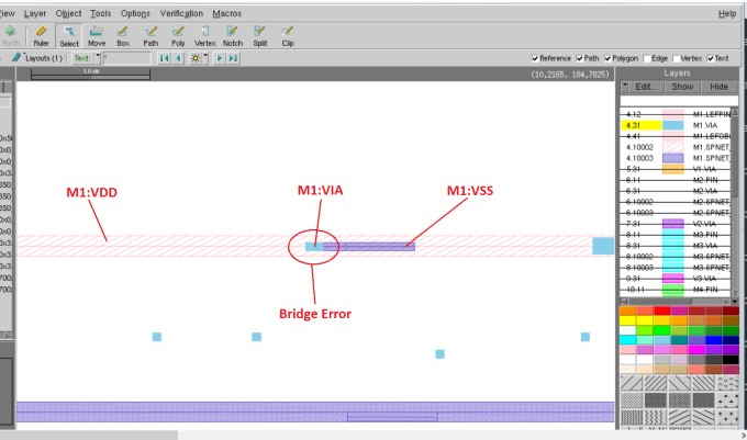
Because of this separation of the objects by their types, debugging of short and bridge errors becomes much easier. These errors can also be displayed visually in the Calibre DESIGNrev™ viewer, enabling designers to more quickly understand the location and cause of these shorts (Figure 4).

Figure 4: This bridge error was not captured in P&R, but was found using the FDI power/ground short detection method (Mentor)
Conclusion
In parallelized implementation flows, full-chip verification is often performed on incomplete and/or incompatible design data to find and remove systemic issues, such as power/ground shorts. The SoC integrator uses this information to triage errors and identify block/IP owners for resolution. Waiting until the majority of blocks are near physical design closure for this verification is impractical, because correcting such issues at that stage requires re-merging of design data, which creates risk to the design schedule. However, mismatches between abstract and physical data can mask the root cause of these errors, making their correction a time-consuming task that can also affect time to tapeout.
Early detection of such violations provides the SoC integrator and block/IP owners with the opportunity to fix them before design data merging and full-chip physical verification. The Calibre FDI utilities provide design teams with a fast, automated flow to perform design integrity checking during implementation. Automated power/ground short checking using abstract LEF/DEF input is one type of design integrity check that can be performed with a minimal amount of user setup prior to full-chip data merging. Adding this type of design integrity checking to the verification flow can significantly reduce the time and resources needed to ensure these violations are removed prior to full-chip verification.
To learn more, download the whitepaper, Early detection of power/ground shorts speeds time to tapeout.
About the authors
James Paris is a senior product engineer with the Design to Silicon division of Mentor, a Siemens business, supporting Calibre design interfaces. Prior to joining Mentor, he was responsible for analog/mixed-signal physical design implementation and flow development for various IC design companies. James holds a BS in computer-aided design engineering and an MBA in marketing.
Armen Asatryan is an R&D technical lead for the Calibre platform at Mentor, a Siemens business. Prior to joining Mentor, he held a variety of R&D management positions in EDA startups, with a focus on database management for yield analysis tools and flow integration with P&R environments. Armen holds a MS in applied mathematics with a focus in Computer Science, and a PhD. in engineering from the Institute for Informatics and Automation Problems of National Academy of Sciences of Armenia.


