One BSIM to rule them all
A change in the way the core compact models are developed has accelerated their development and, for the first time, allowed the models to be used not just for circuit simulation but to help guide process evolution as chipmakers play not only with materials but the shape of finFETs.
Professor Chenming Hu of UC Berkeley described the shift to “forward-looking compact models” in a keynote for the Silicon Integration Initiative (Si2) at the recent Design Automation Conference in San Francisco and how changes in modeling allows one core BSIM model to be used across a range of device types.
“Compact models tend to be done after the development of the [process] technology has been completed,” Hu explained. “With the finFET we changed that but that was because there was such a long incubation time before [the transistor] came online. We started work on the finFET compact model in 2006. That was why we could have it ready in time.
“Developing these models does take a lot of time. And the standardization process takes a long time – that took three years. And it took four years to work on the model. We need to do something different going forward,” Hu said.
“The compact model is really a vehicle for information transfer. We have to capture all of the characteristics of the transistor in a form that an EDA tool can read and a designer can use. The compact model has unusual requirements: it has to be very fast – you have just 10µs to calculate an operating point; and it needs to be very accurate over the full frequency and temperature range. That is pretty difficult. And, on top, it has to be really robust.”
Analytical equations provide speed
“The best way anyone has found to meet those requirements of speed and accuracy is to use analytical equations to describe the transistor. It’s more an art than a science, but it’s art based on science. You start with simple equations to describe a simple structure that are not very different to those found in the introduction of a textbook. But that’s a small part of the model, 15 per cent of the code or less. The rest of the model, which I think is the heart and soul of compact modeling lies in all of the things around it,” Hu explained, referring to the additional equations that describe physical effects, such as mobility, impact ionization, overlap capacitance, and short channel effects.
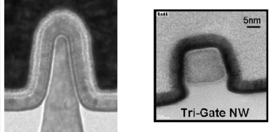
Figure 1 The revised BSIM4 handles different structures such as Intel's trigate and the trigate nanowire from ST/CEA-Leti
Hu said effects such as interactions between multiple fins are taken into account in the additional sub-models that simulate physical effects. “Surrounding that core [model] are dozens of other effects and phenomena that we have to model individually. With the core model, I felt there was a way of doing that better. But for those other effects, I don’t see other approaches replacing them. What else can you do but model them as they come out?”
“Each of these [physical effects] if we want to analyze them carefully will use up the 10µs budget. The art is to find the essence of these physical phenomena: just enough detail to get the accuracy but fast enough to be used across millions of transistors,” said Hu.
Derivatives matter
“Building a table based on measurements will never work,” Hu claimed because the experimental data contains too much extraneous noise that will not just lead to errors when applied to the many transistors needed to model full circuits and chips but make it hard to model derivatives of core parameters such as current and voltage. “If you really want to see the accuracy you have to look into the derivatives, such as transconductance.”
A problem for the existing compact models is that even the 10 per cent of the core model has so far needed to be different between variants of BSIM to account for transistor geometries and styles. “Even that has to change. But we have calculated that we don’t actually need to develop new equations to deliver different geometries,” Hu claimed, pointing to the development of the latest BSIM-CMG model, currently in second beta, which has options to select different types of multigate transistor, from double-gate devices through finFETs to nanowire and pillar transistors.
This unified model will help support what Hu called “forward-looking modeling” where a common, highly flexible core model is married to more detailed models of additional effects controlled by changes to shape and materials.
Hu explained: “A lot of things are happening. A lot of research is going on among the leading companies to keep bringing out better technologies. The germanium finFET is one possibility for 10nm. This is because germanium can have twice the mobility of silicon. That will improve the performance quite significantly. BSIM can model germanium finFETs already but we decided we would look forward. We thought we would not wait for companies to ask for it. We worked with research groups and universities to develop the model. I think it will help with the codevelopment of technologies.”
Models for future materials
The results of the germanium finFET modeling exercise was published in the July 2014 issue of IEEE Electron Device Letters, detailing how the model needed to be changed. Hu said at DAC: “The main improvement we made to the model was the mobility behavior of the germanium material. It’s quite different to that of silicon, specifically how it varies with Vg, the vertical field that carriers experience. We could see 5dB of error in the harmonic distortion if we didn’t make this improvement. This change allows the same BSIM model to be used for germanium – we introduced a toggle switch to select it.”
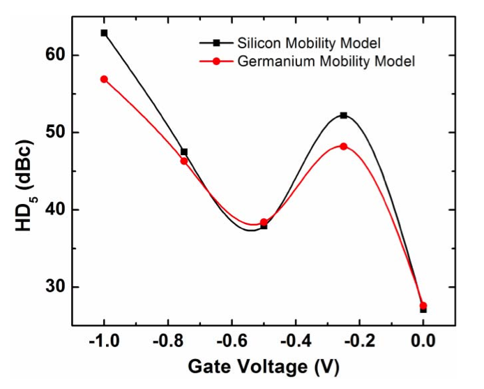
Figure 2 Fifth-order harmonic distortion predicted with silicon and germanium mobility models (Source: UC Berkeley)
The same is now happening for n-channel finFETs. “Germanium is going to be a big help for p-channel performance. But what about n-channel? People are counting on III-V materials. Right now the leading candidate is InGaAs [indium gallium arsenide]. Their hole mobility is actually lower than that of silicon but electron mobility is much higher. Now is the time to get the model ready for people to study whether the performance benefit is really there for certain circuits.”
As with germanium, support for novel III-V materials will be invoked using a command-line switch, as will shape parameters.
“Usually we think of a finFET having a very simple shape. But different companies have published different shapes, all the way to the nanowire. A surface that is not vertical can potentially provide higher mobility because mobility is partially a function of crystal orientation. There are different reasons why people want to play with the structures and even without that just manufacturing variation is going to create shape variation.”
Fin shape considerations
Although fin taper has so far been thought to be bad for device performance, particularly subthreshold leakage and drive current, work on adding surface layers to the fins – TSMC has filed for a patent on one technique – may provide sloped fin structures with ways to add thin layers that have mobility-optimized crystal orientations to the channel.
“The traditional way to do equations for the core model just cannot be done [for variable-shape devices]. But we have found methods to introduce new ways of modeling the structures. We bypass the detailed equation solutions…by looking at it from a higher level. We found a solution not based on details: not based on the micro-parameters but the macro-parameters.”
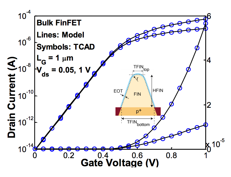
Figure 3 Results from a compact-model simulation compared to TCAD for a trapezoidal finFET (Source: UC Berkeley)
The parameters the UC Berkeley team found are cross-sectional area, the maximum width and the insulation capacitance. “If we know these parameters we don’t need to know the exact shape – an extreme case could be a nanowire. And the channel doping does not have to be uniform.”
“If we know the cross-sectional area, capacitance and the W [width], that is enough to create solid curves. We had to do dozens of these to convince ourselves, often using TCAD as surrogates of actual devices. But we also had the opportunity to get real data and it works very well. We found that it is even faster than the model that is standard for finFETs today,” Hu said, adding that the new model is better for simulating body bias effects. According to simulations, the new model is around 30 per cent faster than its predecessor.
Vertical and FD-SOI structures
Hu claimed the model will be useful for modeling pillar transistors – a vertical nanowire structure being considered for DRAM and NAND devices as these adopt 3DIC architectures.
“There is no reason for these transistors to be symmetrical for the source and drain. You will have different behaviors because there is no guarantee that the doping will be the same at the top and bottom just because of manufacturing variation.”
In addition, UC Berkeley is working on extended ultra-thin body silicon-on-insulator (SOI) models to fit FD-SOI processes and potential successors based on novel materials such as molybdenum disulfide and tungsten diselenide. “In a quarter or two we will have a standard model for FD-SOI.”
Hu concluded: “Structures are coming at a faster rate than ever before. EDA has to respond to that. We can now model germanium and InGaAs finFETs and complex shapes like nano wires. And the FD-SOI model should be coming soon.”
The result should make it easier for circuit designers and process engineers to work on design-technology codevelopment and make more informed decisions about the best path to take for future devices.