Physical verification of 20nm designs through integrated double-patterning analysis and repair
Finding and fixing double patterning problems in 20nm designs
The double-patterning technology (DPT) that means we can continue to use 193nm lithography to produce features at a 64nm pitch in 20nm processes is a breakthrough for manufacturing but an added complication for design. In double patterning, features that are too close together to be resolved with conventional lithography are separated onto two masks, which are exposed sequentially, with an etch step in between, to form the necessary densely packed features.
Designers must create layouts that can be split (‘decomposed’) into two layers, a process known as coloring, after map-coloring theory. Achieving such layouts means following new design rules that encapsulate the limitations of the lithographic process and prohibit two polygons of the same color from having particular geometric relationships.
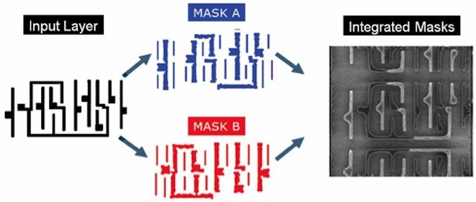
Figure 1
In double patterning, an input layer is split onto two masks to overcome the limitations of 193nm lithography (Source: Synopsys – click image to enlarge)
Physical designers have to work with these new rules during placement and routing, considering the costs of decomposability alongside other costs such as timing, power and area. The physical verification process also has to change, so that it can show that an entire layout can be successfully split onto two masks in a way that meets the foundry’s specifications.
Achieving decomposability
Although foundries will often decompose a layout themselves so that they can optimise the resultant masks for manufacturability, producing decomposable designs means being able to show that applying the foundry rules to a layout can result in successful mask assignments.
The essence of the coloring problem is to create layouts made up of closed loops of polygons (so-called ‘cycles’) that can be given alternating colors along the whole length of the loop. Physical verification tools such as Synopsys’s IC Validator include analysis engines that enable users to define complex geometric relationships, such as the minimum spacing between polygon edges and the corners of facing sides or line ends assigned to the same mask, and then apply them to a candidate design. More elaborate rules allow single polygons to be subdivided on to two masks (a process known as ‘stitching’), which enables greater design freedom by offering a way to avoid some coloring violations.
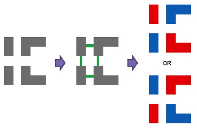
Figure 2
In basic decomposition, you identify densely packed features and color them to be patterned by different masks (Source: Synopsys – click image to enlarge)
IC Validator includes a foundry-certified coloring engine that takes a layout and the rules defining the color-critical relationships between polygons, and decomposes the layout into two colors. If this process results in adjacent polygons being given the same color, the tool flags a violation and shows the user on the layout.
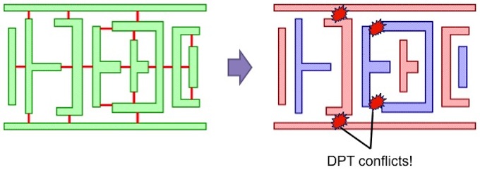
Figure 3
The odd number of polygons in this cycle leads to a coloring violation (Source: Synopsys – click image to enlarge)
This means designers can debug DPT conflicts alongside standard DRC errors, and that tools further down the design flow can use the tool’s coloring output for further analysis. The tool also works across all levels of hierarchy, which is important for finding coloring violations on very long cycles.
Embedding the coloring engine in the physical verification tool and making it available within the implementation environment, through tool-integration technology such as Synopsys’ award-winning In-Design link between IC Validator and IC Compiler, it can be used throughout the flow, from library design through to final layout signoff.
Meeting DPT requirements in library development
Double-patterning requirements have to be taken into account in both the design and placement of 20nm cell libraries.
Cell designers must ensure that their cell layouts can be safely decomposed into two colors, using physical verification tools to check that their work will meet this requirement and to suggest possible adjustments if it doesn’t. Cell designers also need to think about possible interactions between the cells they design when they are placed adjacent to each other. One way to overcome this issue is to build enough space into every cell that they can’t create coloring violations. The other is to design cells without this margin and rely on the placer to avoid any potential violations caused by cell adjacencies. Both approaches are supported by In-Design technology, which seamlessly couples signoff-quality analysis in IC Validator to the placement engine in IC Compiler.
Here’s an example of a 20nm cell library in which the designer has created an XOR gate and wants to know whether it can be successfully decomposed and its properties in placement.
The cell is first decomposed according to some basic conditions: both power rails must be assigned to the same color and polygons must not be stitched. This approach results in DPT conflicts.
Figure 4
In this cell design, first the critical relationships between polygons are established, and then the coloring algorithm is run, resulting in coloring violations (Source: Synopsys – click image to enlarge)
However, the target manufacturing process for the cell library does allow polygons to be stitched, so a second pass is undertaken (below) in which the areas that can be safely stitched are determined first on the basis of color spacing rules, and o the basis of color overlap rules.
Figure 5
Given the freedom to use stitching, first the sub-regions of polygons that are not critical for DPT are marked (left), and then legalized according to color overlap rules (right) (Source: Synopsys – click image to enlarge)
In the last step, the areas in which stitching is allowed are temporarily removed so that the coloring algorithm can decompose the color-critical regions. The stitchable regions are then added back into the design and colored based on their local context. The end result is a cell that meets the decomposition rules.
Figure 6
Areas in which stitching is allowed are first removed from the coloring-critical problem (left), so that the coloring algorithm can color the critical areas, and then evaluate and color the stitchable regions (right) (Source: Synopsys – click image to enlarge)
The final cell can now be used in layouts without DPT conflicts.
Automating DPT repair
Fixing DPT violations manually can be a lengthy and uncertain process: because of the length of some polygon cycles it’s hard to know whether an adjustment in one area of a chip will cause a violation somewhere else on it.
Automated tools can look at a violation, find all the polygons involved and then offer various repair options. Synopsys’s IC Validator, working through In-Design technology, can calculate these costs and then guide IC Compiler’s router through a cost-ranked queue of repairs. This approach helps the design evolve naturally and eliminates lengthy and uncertain manual interventions.
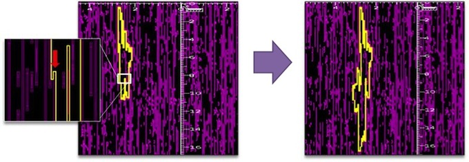
Here’s an example in which an odd-cycle violation has been identified on the M3 layer.
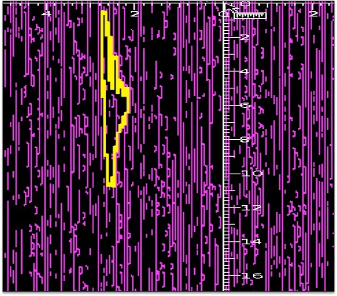
Figure 7
A long-range DPT violation on M3 (Source: Synopsys – click image to enlarge)
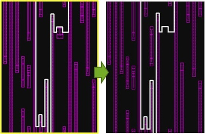
The cycle initially seems relatively benign, with about 25 shapes and multiple apparent opportunities to adjust the shapes to undo the violation. The designer attempts to break the cycle by moving two neighboring shapes in the lower part of the cycle far enough part that they shouldn’t interact enough to create a double-patterning issue. Rechecking the resultant layout reveals that the cycle has actually been enlarged.
Figure 8
Manually repairing a DPT violation – attempted fix #1 (Source: Synopsys – click image to enlarge)
The designer tries again, selecting a line-end that can be pulled back to break a double-patterning interaction with a neighboring shape.
Figure 9
Manually repairing a DPT violation – attempted fix #2 (Source: Synopsys – click image to enlarge)
Another post-fix analysis shows that a different odd cycle has emerged, this time involving about 50 shapes (above). At this point it is not clear how the designer can avoid going through a lengthy set of fix-then-verify loops until something works. Recognizing that this is a productivity issue, IC Validator offers automatic DPT repair.
Figure 10
DPT ADR – automatically repairing a DPT violation (Source: Synopsys – click image to enlarge)
In the example design, the automated repair mechanism identifies a critical link in the original odd cycle, and moves one shape to break that link and fix the problem without creating a new one. The repair resolves the DPT violation, meets design rule checks, is minimally invasive from a physical standpoint, and doesn’t degrade the chip’s timing.
Conclusions
The shift to 20nm processes brings manufacturing issues into the heart of the design process, especially in terms of meeting the requirements of double-patterning lithography. Coloring for decomposability checking has become an important part of a physical verification flow. Integration between physical design and verification, such as Synopsys’ In-Design technology with IC Validator and IC Compiler, boosts productivity by ensuring that coloring issues can be resolved automatically throughout the design process, from library generation through to final layout sign-off. This reduces late-stage surprises and risk of schedule delays that could otherwise have been expected due to the additional complexity of 20nm processes.
IC Validator is already in use on 20nm designs and has been validated by the leading 20nm foundries.
Authors
Paul Friedberg, corporate applications engineering, Synopsys
Stelios Diamantidis, product marketing, Synopsys
Links
Find out more about Synopsys’s 20nm offering here
Synopsys
700 East Middlefield RoadMountain View, CA 94043
Phone: (650) 584-5000 or
(800) 541-7737
